Toyota 4Runner: Parts Location
PARTS LOCATION
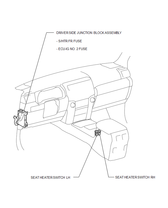
ILLUSTRATION
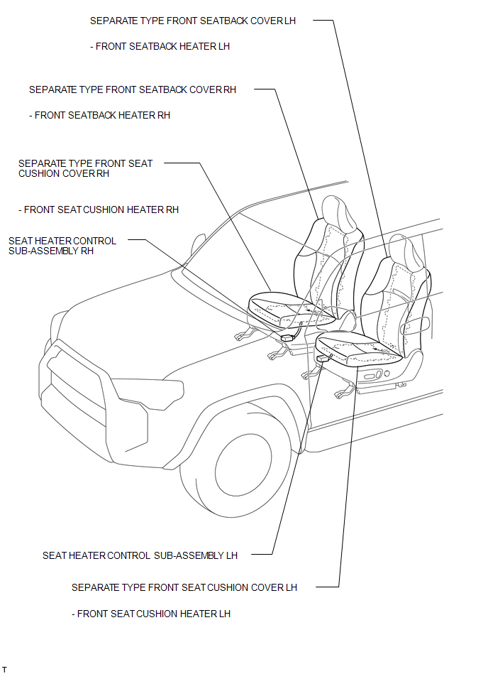
ILLUSTRATION
 Precaution
PRECAUTION
1. IGNITION SWITCH EXPRESSION
HINT:
The type of ignition switch used on this model differs depending on the specifications
of the vehicle. The expressions listed in the table below are ...
 System Diagram
SYSTEM DIAGRAM
...
Other materials about Toyota 4Runner:
Reassembly
REASSEMBLY
PROCEDURE
1. INSTALL FRONT PROPELLER SHAFT UNIVERSAL JOINT SPIDER BEARING
HINT:
Use the same procedure for all propeller shaft universal joint spider bearing.
(a) Apply MP grease to a new spider and spider bearing.
NOTICE:
Be c ...
CD Sound Skips
CAUTION / NOTICE / HINT
NOTICE:
After replacing the navigation receiver assembly of vehicles subscribed to pay-type
satellite radio broadcasts, XM radio ID registration is necessary.
PROCEDURE
1.
CHECK DISC
(a) ...
© 2016-2026 | www.to4runner.net

0.0106
0.0106