Toyota 4Runner: Parts Location
Toyota 4Runner Service Manual / Vehicle Interior / Supplemental Restraint Systems / Airbag System / Parts Location
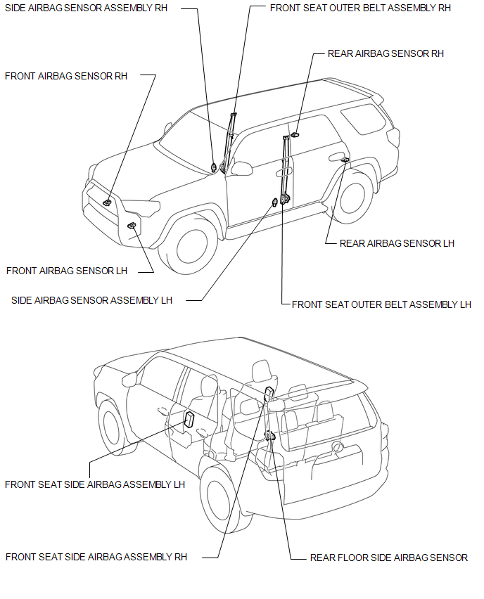
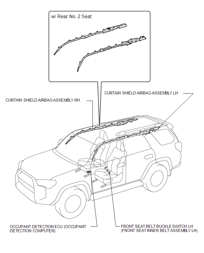
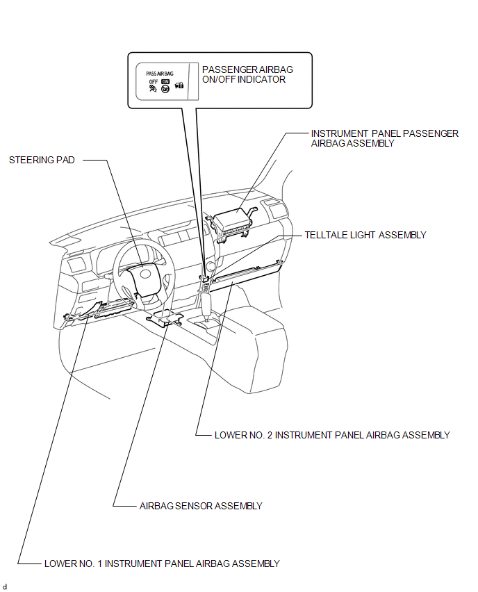
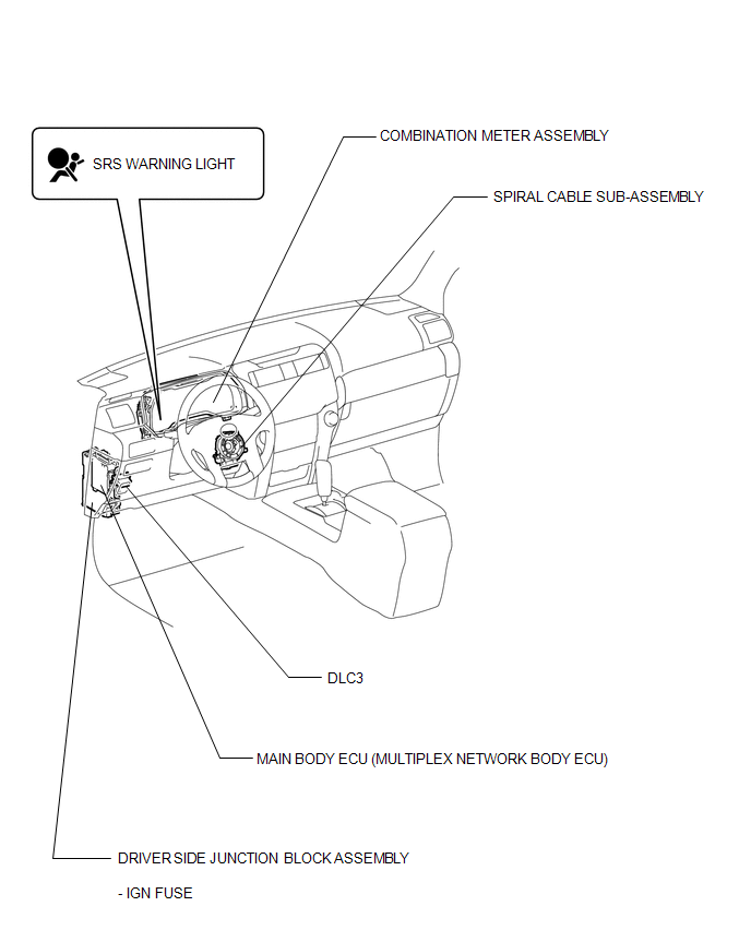
PARTS LOCATION
ILLUSTRATION
ILLUSTRATION
ILLUSTRATION
ILLUSTRATION
 Precaution
PRECAUTION
CAUTION:
This vehicle is equipped with a Supplemental Restraint System (SRS),
which consists of a steering pad, instrument panel passenger airbag, curtain
shield airbag, f ...
 System Diagram
SYSTEM DIAGRAM
Transmitting ECU
(Transmitter)
Receiving ECU
Signal
Communication Method
Center Airbag Sensor
ECM
...
Other materials about Toyota 4Runner:
Installation
INSTALLATION
PROCEDURE
1. INSTALL FRONT PROPELLER SHAFT ASSEMBLY
(a) Align the matchmarks on the yoke and differential flange.
(b) Install the propeller shaft assembly with the 4 washers, 4 bolts and 4 nuts.
Torque:
88 N·m {899 kgf·cm, 65 ft·lbf}
(c ...
Transmitter ID1 Error (C2141/41-C2145/45)
DESCRIPTION
The tire pressure warning valve and transmitters that are installed in the tire
and wheel assemblies measure the air pressure of the tires. The measured values
are transmitted to the tire pressure warning antenna and receiver on the body as
...
© 2016-2026 | www.to4runner.net

0.0281
0.0281