Toyota 4Runner: Parts Location
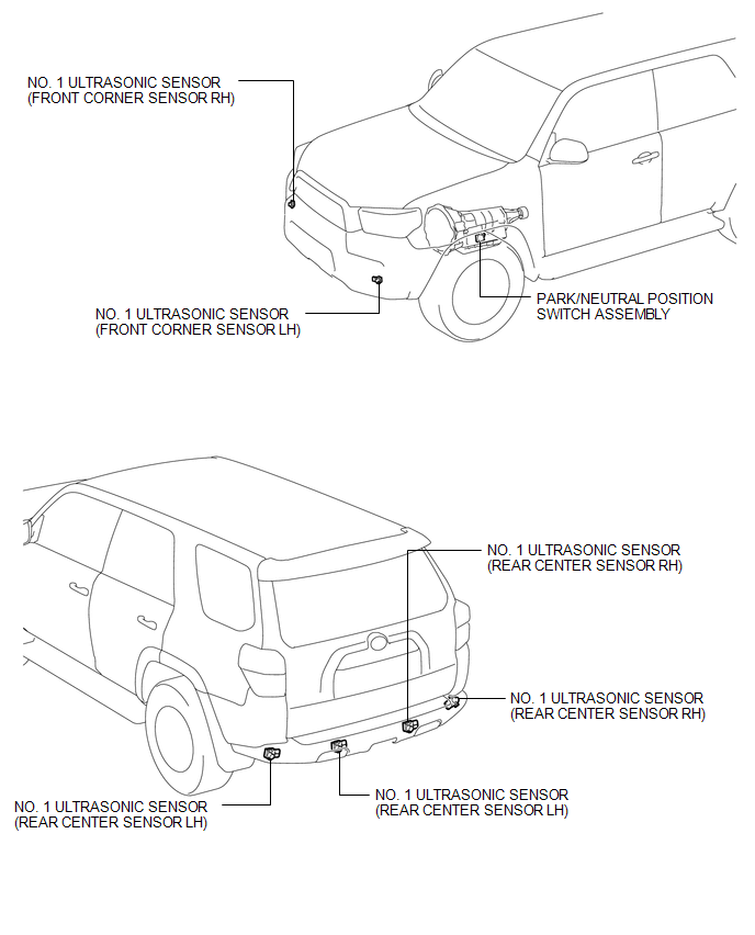
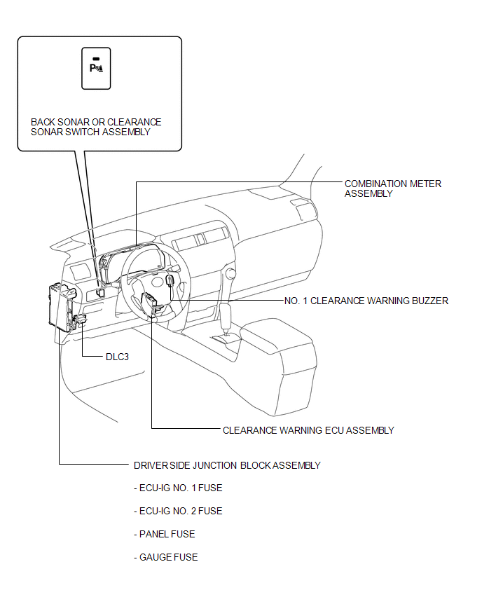
PARTS LOCATION
ILLUSTRATION
ILLUSTRATION
 Precaution
PRECAUTION
1. IGNITION SWITCH EXPRESSION
HINT:
The type of ignition switch used on this model differs according to the specifications
of the vehicle. The expressions listed in the table below are ...
 System Diagram
SYSTEM DIAGRAM
...
Other materials about Toyota 4Runner:
Removal
REMOVAL
PROCEDURE
1. DISCONNECT CABLE FROM NEGATIVE BATTERY TERMINAL
NOTICE:
When disconnecting the cable, some systems need to be initialized after the cable
is reconnected (See page ).
2. DISCONNECT CABLE FROM POSITIVE BATTERY TERMINAL
3. REMOVE BAT ...
IG Power Source Circuit
DESCRIPTION
When the ignition switch is turned to ON, the IG power source circuit supplies
positive (+) voltage to the power steering ECU assembly.
WIRING DIAGRAM
CAUTION / NOTICE / HINT
NOTICE:
Inspect the fuses for circuits related to this system be ...
© 2016-2026 | www.to4runner.net

0.0065
0.0065