Toyota 4Runner: Parts Location
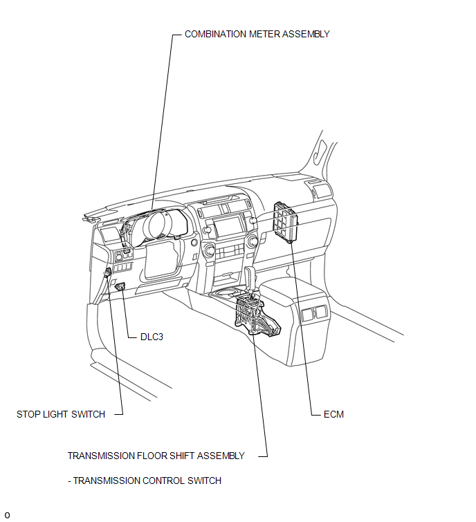
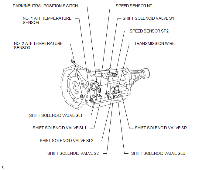
PARTS LOCATION
ILLUSTRATION
ILLUSTRATION
 Definition Of Terms
DEFINITION OF TERMS
Term
Definition
Monitor description
Description of what the ECM monitors and how it detects malfunctions
(monitoring purpose ...
 System Diagram
SYSTEM DIAGRAM
The configuration of the electronic control system for the A750E automatic transmission
is as shown in the following chart.
...
Other materials about Toyota 4Runner:
Rear Clearance Sonar Sensor LH Circuit
DESCRIPTION
The ultrasonic sensor sends and receives ultrasonic waves. Based on the received
wave, the sensor calculates the approximate distance between the vehicle and the
obstacle, and sends the distance value as a signal to the clearance warning ECU
...
Portable Player cannot be Connected Manually/Automatically
CAUTION / NOTICE / HINT
HINT:
Some versions of "Bluetooth" compatible audio players may not function, or the
function may be limited using the navigation receiver assembly, even if the portable
audio player itself can play files (See page ).
...
© 2016-2026 | www.to4runner.net

0.0276
0.0276