Toyota 4Runner: Power Steering ECU Communication Stop Mode
DESCRIPTION
|
Detection Item |
Symptom |
Trouble Area |
|---|---|---|
|
Power Steering ECU Communication Stop Mode |
Either condition is met:
|
|
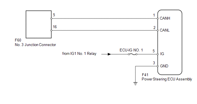
WIRING DIAGRAM
CAUTION / NOTICE / HINT
NOTICE:
Inspect the fuses for circuits related to this system before performing the following inspection procedure.
HINT:
Operating the ignition switch, any switches or any doors triggers related ECU and sensor communication with the CAN, which causes resistance variation.
PROCEDURE
|
1. |
DISCONNECT CABLE FROM NEGATIVE BATTERY TERMINAL |
(a) Disconnect the cable from the negative (-) battery terminal before measuring the resistances of the main wire and branch wire.
CAUTION:
Wait at least 90 seconds after disconnecting the cable from the negative (-) battery terminal to disable the SRS system.
NOTICE:
When disconnecting the cable, some systems need to be initialized after the cable
is reconnected (See page .gif) ).
).
|
.gif)
|
2. |
CHECK FOR OPEN IN CAN BUS WIRE (POWER STEERING ECU ASSEMBLY BRANCH WIRE) |
|
(a) Disconnect the F41 power steering ECU assembly connector. |
|
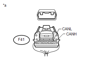
(b) Measure the resistance according to the value(s) in the table below.
Standard Resistance:
|
Tester Connection |
Switch Condition |
Specified Condition |
|---|---|---|
|
F41-1 (CANH) - F41-2 (CANL) |
Ignition switch off |
54 to 69 Ω |
|
*a |
Rear view of wire harness connector (to Power Steering ECU Assembly) |
| NG | .gif) |
REPAIR OR REPLACE POWER STEERING ECU ASSEMBLY BRANCH WIRE OR CONNECTOR (CANH, CANL) |
|
|
3. |
CHECK HARNESS AND CONNECTOR (POWER STEERING ECU ASSEMBLY - BATTERY AND BODY GROUND) |
|
(a) Connect the cable to the negative (-) battery terminal. NOTICE: When disconnecting the cable, some systems need to be initialized after
the cable is reconnected (See page |
|
(b) Measure the resistance according to the value(s) in the table below.
Standard Resistance:
|
Tester Connection |
Condition |
Specified Condition |
|---|---|---|
|
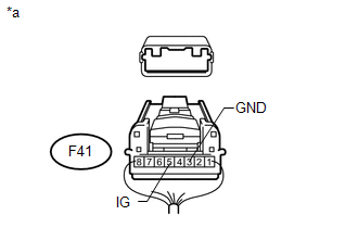
F41-3 (GND) - Body ground |
Always |
Below 1 Ω |
(c) Measure the voltage according to the value(s) in the table below.
Standard Voltage:
|
Tester Connection |
Switch Condition |
Specified Condition |
|---|---|---|
|
F41-5 (IG) - Body ground |
Ignition switch ON |
11 to 14 V |
|
*a |
Rear view of wire harness connector (to Power Steering ECU Assembly) |
| OK | |
REPLACE POWER STEERING ECU ASSEMBLY |
| NG | |
REPAIR OR REPLACE HARNESS OR CONNECTOR |
 Air Conditioning Amplifier Communication Stop Mode
DESCRIPTION
Detection Item
Symptom
Trouble Area
Air Conditioning Amplifier Communication Stop Mode
Either condition is met:
...
 Steering Angle Sensor Communication Stop Mode
DESCRIPTION
Detection Item
Symptom
Trouble Area
Steering Angle Sensor Communication Stop Mode
Either condition is met:
" ...
Other materials about Toyota 4Runner:
Only Wireless Control Function is Inoperative
DESCRIPTION
The door control receiver receives signals from the transmitter and sends these
signals to the main body ECU. The main body ECU then controls all the doors by sending
lock/unlock signals to each door.
WIRING DIAGRAM
CAUTION / NOTICE / HINT ...
Installation
INSTALLATION
PROCEDURE
1. INSTALL POWER WINDOW REGULATOR MOTOR ASSEMBLY LH
NOTICE:
The regulator arm must be below the intermediate position when installing the
rear power window regulator motor assembly.
(a) Using a T25 "TORX" sock ...

0.0264