Toyota 4Runner: Pressure Sensor Malfunction / Upside (C1812/12)
DESCRIPTION
In the KDSS hydraulic circuit, the fluid is contained under pressure. If the fluid temperature is 20°C (68°F), the pressure is approximately 3.0 MPa (30.6 kgf/cm2, 435 psi).
|
DTC Code |
DTC Detection Condition |
Trouble Area |
|---|---|---|
|
C1812/12 |
One of the following conditions is met:
|
|
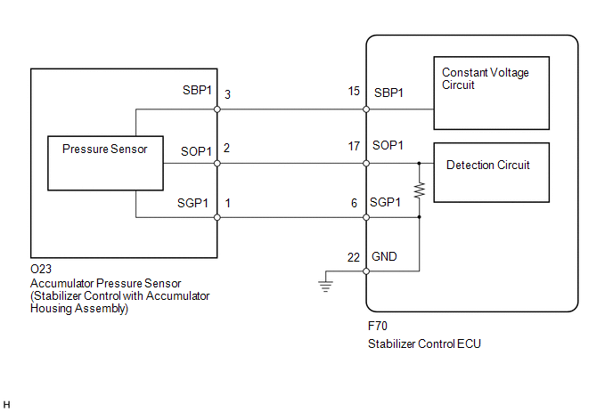
WIRING DIAGRAM
PROCEDURE
|
1. |
READ VALUE USING TECHSTREAM (OIL PRESSURE SENSOR) |
NOTICE:
- Perform the inspection on a level surface.
- Perform the inspection with the vehicle empty.
- Make sure that the wheels are on the ground and facing straight ahead.
- Perform the inspection with the vehicle load completely on the suspension.
(a) Turn the ignition switch off.
(b) Connect the Techstream to the DLC3.
(c) Turn the ignition switch to ON.
(d) Turn the Techstream on.
(e) Enter the following menus: Chassis / KDSS / Data List.
(f) Select the item below in the Data List, and read the value displayed on the Techstream.
KDSS|
Tester Display |
Measurement Item/Range |
Normal Condition |
Diagnostic Note |
|---|---|---|---|
|
Oil Pressure Sensor |
Oil pressure sensor/ Min.: -784.79 MPa (-8002.66 kgf/cm2, -113794.55 psi) Max.: 784.76 MPa (8002.35 kgf/cm2, 113790.20 psi) |
2.6 MPa (26.5 kgf/cm2, 377 psi) to 3.0 MPa (30.6 kgf/cm2, 435 psi): When vehicle stopped and fluid temperature 20°C (68°F) |
- |
(g) Check the fluid pressure.
OK:
2.6 MPa (26.5 kgf/cm2, 377 psi) to 3.0 MPa (30.6 kgf/cm2, 435 psi)
| NG | .gif) |
GO TO STEP 3 |
|
.gif)
|
2. |
RECONFIRM DTC |
(a) Clear the DTCs (See page .gif) ).
).
(b) Check for DTCs (See page ).
Result
|
Result |
Proceed to |
|---|---|
|
DTC is output |
A |
|
DTC is not output |
B |
| A | |
REPLACE STABILIZER CONTROL ECU |
| B | |
USE SIMULATION METHOD TO CHECK |
|
3. |
INSPECT STABILIZER CONTROL ECU (SBP1 VOLTAGE) |
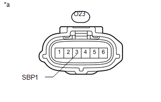
(a) Connect the stabilizer control ECU connector.
(b) Disconnect the stabilizer control with accumulator housing connector.
|
(c) Measure the voltage according to the value(s) in the table below. Standard Voltage:
|
|
| NG | |
GO TO STEP 7 |
|
|
4. |
CHECK HARNESS AND CONNECTOR (STABILIZER CONTROL ECU - ACCUMULATOR PRESSURE SENSOR) |
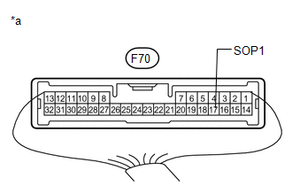
(a) Disconnect the stabilizer control ECU connector.
(b) Disconnect the stabilizer control with accumulator housing connector.
(c) Measure the resistance according to the value(s) in the table below.
Standard Resistance:
|
Tester Connection |
Condition |
Specified Condition |
|---|---|---|
|
F70-17 (SOP1) - O23-2 (SOP1) |
Always |
Below 1 Ω |
|
F70-17 (SOP1) - Body ground |
Always |
10 kΩ or higher |
|
F70-6 (SGP1) - O23-1 (SGP1) |
Always |
Below 1 Ω |
|
F70-6 (SGP1) - Body ground |
Always |
10 kΩ or higher |
| NG | |
REPAIR OR REPLACE HARNESS OR CONNECTOR |
|
|
5. |
INSPECT ACCUMULATOR PRESSURE SENSOR (OUTPUT VOLTAGE) |
(a) Connect the stabilizer control ECU connector.
(b) Connect the stabilizer control with accumulator housing connector.
|
(c) Measure the voltage according to the value(s) in the table below. Standard Voltage:
|
|
| OK | |
REPLACE STABILIZER CONTROL ECU |
|
|
6. |
READ VALUE USING TECHSTREAM (OIL PRESSURE SENSOR) |
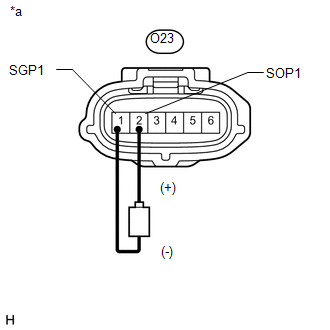
(a) Disconnect the stabilizer control with accumulator housing connector.
(b) Connect the stabilizer control ECU connector.
(c) Connect the Techstream to the DLC3.
(d) Turn the ignition switch to ON.
(e) Turn the Techstream on.
(f) Enter the following menus: Chassis / KDSS / Data List.
(g) Select the item below in the Data List, and read the value displayed on the Techstream.
KDSS|
Tester Display |
Measurement Item/Range |
Normal Condition |
Diagnostic Note |
|---|---|---|---|
|
Oil Pressure Sensor |
Oil pressure sensor/ Min.: -784.79 MPa (-8002.66 kgf/cm2, -113794.55 psi) Max.: 784.76 MPa (8002.35 kgf/cm2, 113790.20 psi) |
2.6 MPa (26.5 kgf/cm2, 377 psi) to 3.0 MPa (30.6 kgf/cm2, 435 psi): When vehicle stopped and fluid temperature 20°C (68°F) |
- |
|
(h) Using a 1.5 V dry cell battery, connect the positive (+) lead to terminal 2 (SOP1) of the stabilizer control with accumulator housing connector and the negative (-) lead to terminal 1 (SGP1), and check that the Data List display changes. OK: Data List display changes. Text in Illustration
|
|
| OK | |
REPLACE STABILIZER CONTROLWITH ACCUMULATORHOUSING ASSEMBLY |
| NG | |
REPLACE STABILIZER CONTROL ECU |
|
7. |
CHECK HARNESS AND CONNECTOR (STABILIZER CONTROL ECU - ACCUMULATOR PRESSURE SENSOR) |
(a) Disconnect the stabilizer control ECU connector.
(b) Disconnect the stabilizer control with accumulator housing connector.
(c) Measure the resistance according to the value(s) in the table below.
Standard Resistance:
|
Tester Connection |
Condition |
Specified Condition |
|---|---|---|
|
F70-15 (SBP1) - O23-3 (SBP1) |
Always |
Below 1 Ω |
|
F70-15 (SBP1) - Body ground |
Always |
10 kΩ or higher |
| OK | |
REPLACE STABILIZER CONTROL ECU |
| NG | |
REPAIR OR REPLACE HARNESS OR CONNECTOR |
 Low Pressure Malfunction in Upside of KDSS System (C1851/51,C1853/53)
DESCRIPTION
In the KDSS hydraulic circuit, the fluid is contained under pressure. If the
fluid temperature is 20°C (68°F), the pressure is approximately 3.0 MPa (30.6 kgf/cm2,
435 psi).
...
 Accumulator Solenoid Malfunction / Upside (C1831/31,C1832/32)
DESCRIPTION
The stabilizer control ECU receives information from the steering angle sensor,
skid control ECU (speed signal) and yaw rate and acceleration sensor via CAN communication.
Based on th ...
Other materials about Toyota 4Runner:
Setting a cellular phone
Registering a cellular phone in the hands-free phone system allows the
system to function. The following functions can be used for registered cellular
phones:
Functions and operation procedures
To enter the menu for each function, follow the steps below ...
Rear Floor Airbag Sensor Malfunction (B1675/82)
DESCRIPTION
The rear floor side airbag sensor consists of the diagnostic circuit, rear floor
deceleration sensor, etc.
If the center airbag sensor receives signals from the rear floor deceleration
sensor, it determines whether the SRS should be activated ...

0.0164