Toyota 4Runner: Pressure Sensor or Switch (C1254)
DESCRIPTION
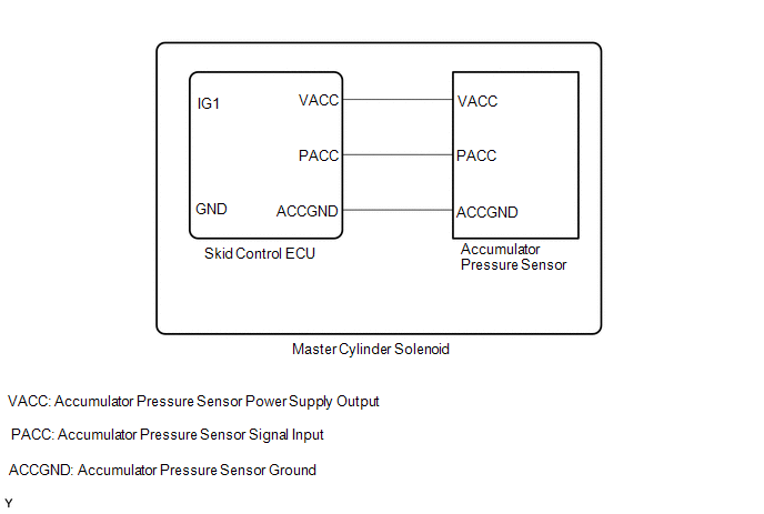
The accumulator pressure sensor is connected to the skid control ECU in the master cylinder solenoid.
|
DTC Code |
DTC Detection Condition |
Trouble Area |
|---|---|---|
|
C1254 |
There is an accumulator pressure sensor malfunction (the fluid pressure does not change when the pump operates or when the brake is applied). |
Master cylinder solenoid (Accumulator pressure sensor) |
CAUTION / NOTICE / HINT
NOTICE:
When replacing the master cylinder solenoid, perform calibration (See page
.gif) ).
).
PROCEDURE
|
1. |
READ VALUE USING TECHSTREAM (ACCUMULATOR SENSOR) |
(a) Turn the ignition switch off.
(b) Connect the Techstream to the DLC3.
(c) Depress the brake pedal more than 40 times.
(d) Turn the ignition switch to ON.
(e) Turn the Techstream on.
(f) Enter the following menus: Chassis / ABS/VSC/TRAC / Data List.
ABS/VSC/TRAC|
Tester Display |
Measurement Item/Range |
Normal Condition |
Diagnostic Note |
|---|---|---|---|
|
Accumulator Sensor |
Accumulator pressure sensor reading/ Min.: 0.00 V, Max.: 5.00 V |
3.58 to 5 V |
If the value is constant regardless of the pump operation, an accumulator pressure sensor malfunction is suspected. |
(g) Check the accumulator output value.
Result|
Result |
Proceed to |
|---|---|
|
Output value is within "Normal Condition" range |
A |
|
Output value is out of "Normal Condition" range |
B |
|
Output value is constant regardless of pump operation |
| B | .gif) |
REPLACE MASTER CYLINDER SOLENOID |
|
.gif)
|
2. |
RECONFIRM DTC |
(a) Clear the DTCs (See page ).
(b) Turn the ignition switch off.
(c) Depress the brake pedal more than 40 times.
(d) Turn the ignition switch to ON.
(e) Wait until the pump motor stops.
(f) Wait for 15 minutes.
(g) Depress the brake pedal and release it.
(h) Check if the same DTC is output (See page
).
|
Result |
Proceed to |
|---|---|
|
DTC is output |
A |
|
DTC is not output |
B |
| A | |
REPLACE MASTER CYLINDER SOLENOID |
| B | |
USE SIMULATION METHOD TO CHECK |
 Pump Motor Relay (C1253)
DESCRIPTION
The motor relay (semiconductor relay) is built into the master cylinder solenoid
and drives the pump motor based on a signal from the skid control ECU.
DTC Code
D ...
 Accumulator Low Pressure (C1256)
DESCRIPTION
Refer to DTC C1254 (See page ).
DTC Code
DTC Detection Condition
Trouble Area
C1256
The fluid pressure inside the accumulato ...
Other materials about Toyota 4Runner:
Turn signal lever
The turn signal lever can be used to show the following intentions of the
driver:
1. Right turn 2. Left turn 3. Lane change to the right (push and hold the
lever partway) The right hand signals will flash until you release the lever.
4. Lane change to ...
Problem Symptoms Table
PROBLEM SYMPTOMS TABLE
HINT:
Use the table below to help determine the cause of problem symptoms.
If multiple suspected areas are listed, the potential causes of the symptoms
are listed in order of probability in the "Suspected Area" ...

0.0075