Toyota 4Runner: Radio Receiver
Components
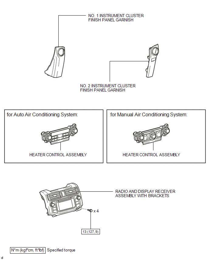
COMPONENTS
ILLUSTRATION
ILLUSTRATION
Removal
REMOVAL
PROCEDURE
1. REMOVE NO. 1 INSTRUMENT CLUSTER FINISH PANEL GARNISH
.gif)
2. REMOVE NO. 2 INSTRUMENT CLUSTER FINISH PANEL GARNISH
3. REMOVE HEATER CONTROL ASSEMBLY
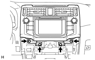
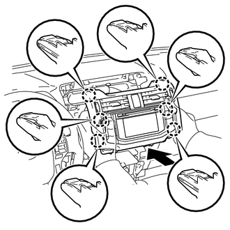
4. REMOVE RADIO AND DISPLAY RECEIVER ASSEMBLY WITH BRACKETS
|
(a) Remove the 4 bolts. |
|
|
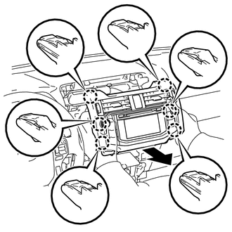
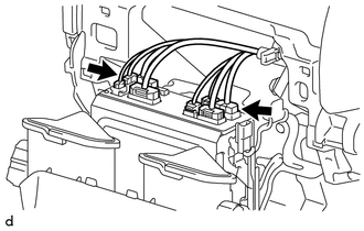
(b) Pull the radio and display receiver assembly with brackets as shown in the illustration to detach the 6 claws on the backside of the radio and display receiver assembly with brackets. |
|
|
(c) Disconnect each connector to remove the radio and display receiver assembly with brackets. |
|
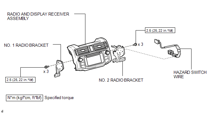
5. REMOVE HAZARD SWITCH WIRE
|
(a) Detach the 2 clamps. |
|
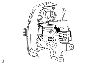
(b) Disconnect the connector to remove the hazard switch wire.
6. REMOVE NO. 1 RADIO BRACKET
|
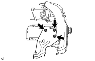
(a) Remove the 3 screws and No. 1 radio bracket. |
|
7. REMOVE NO. 2 RADIO BRACKET
|
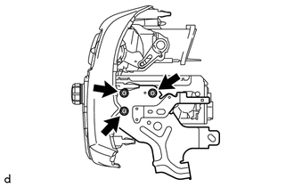
(a) Remove the 3 screws and No. 2 radio bracket. |
|
Installation
INSTALLATION
PROCEDURE
1. INSTALL NO. 2 RADIO BRACKET
(a) Install the No. 2 radio bracket with the 3 screws.
Torque:
2.5 N·m {25 kgf·cm, 22 in·lbf}
2. INSTALL NO. 1 RADIO BRACKET
(a) Install the No. 1 radio bracket with the 3 screws.
Torque:
2.5 N·m {25 kgf·cm, 22 in·lbf}
3. INSTALL HAZARD SWITCH WIRE
(a) Connect the connector.
(b) Attach the 2 clamps to install the hazard switch wire.
4. INSTALL RADIO AND DISPLAY RECEIVER ASSEMBLY WITH BRACKETS
(a) Connect each connector.
|
(b) Insert the radio and display receiver assembly with brackets to attach the 6 claws on its backside. NOTICE: When inserting the radio and display receiver assembly with brackets, do not press its knobs on it. |
|
(c) Install the radio and display receiver assembly with brackets with the 4 bolts.
Torque:
13 N·m {127 kgf·cm, 9 ft·lbf}
5. INSTALL HEATER CONTROL ASSEMBLY
.gif)
6. INSTALL NO. 2 INSTRUMENT CLUSTER FINISH PANEL GARNISH
7. INSTALL NO. 1 INSTRUMENT CLUSTER FINISH PANEL GARNISH
 Radio Antenna Cord
Components
COMPONENTS
ILLUSTRATION
ILLUSTRATION
ILLUSTRATION
Removal
REMOVAL
PROCEDURE
1. DISCONNECT CABLE FROM NEGATIVE BATTERY TERMINAL
CAUTION:
Wait at least 90 seconds after di ...
 Rear Door Speaker
Components
COMPONENTS
ILLUSTRATION
Removal
REMOVAL
CAUTION / NOTICE / HINT
HINT:
Use the same procedure for the RH and LH sides.
The procedure listed below is for the LH side. ...
Other materials about Toyota 4Runner:
Rear No. 1 Seat Inner Belt Assembly(for 60/40 Split Double-folding Seat Type
Rh Side)
Components
COMPONENTS
ILLUSTRATION
Removal
REMOVAL
PROCEDURE
1. DISCONNECT REAR NO. 1 SEAT OUTER BELT ASSEMBLY RH
(a) Pull the rear seat cushion band, release the lock and lift up the
back of the seat cushion to rotate it forward.
...
Diagnosis Circuit
DESCRIPTION
DTC output mode is set by connecting terminals TC and CG of the DLC3.
DTCs are output by the blinking of the SRS warning light.
HINT:
When each warning light continues blinking, a ground short in the wiring
of terminal TC of the DLC ...

0.0262