Toyota 4Runner: Rear Clearance Sonar Sensor RH Circuit
DESCRIPTION
The ultrasonic sensor sends and receives ultrasonic waves. Based on the received wave, the sensor calculates the approximate distance between the vehicle and the obstacle, and sends the distance value as a signal to the clearance warning ECU assembly.
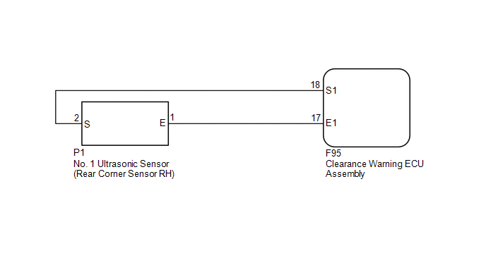
WIRING DIAGRAM
PROCEDURE
|
1. |
REPLACE NO. 1 ULTRASONIC SENSOR (REAR CORNER SENSOR RH) |
(a) Remove the No. 1 ultrasonic sensor (rear corner sensor RH) (See page
.gif) ).
).
(b) Inspect the No. 1 ultrasonic sensor (rear corner sensor RH) (See page
).
| NG | .gif) |
REPLACE NO. 1 ULTRASONIC SENSOR (REAR CORNER SENSOR RH) |
|
.gif)
|
2. |
CHECK HARNESS AND CONNECTOR (REAR CORNER SENSOR RH - CLEARANCE WARNING ECU ASSEMBLY) |
(a) Disconnect the P1 No. 1 ultrasonic sensor (rear corner sensor RH) connector.
(b) Disconnect the F95 clearance warning ECU assembly connector.
(c) Measure the resistance according to the value(s) in the table below.
Standard Resistance:
|
Tester Connection |
Condition |
Specified Condition |
|---|---|---|
|
P1-1 (E) - F95-17 (E1) |
Always |
Below 1 Ω |
|
P1-2 (S) - F95-18 (S1) |
Always |
Below 1 Ω |
|
P1-1 (E) - Body ground |
Always |
10 kΩ or higher |
|
P1-2 (S) - Body ground |
Always |
10 kΩ or higher |
| OK | |
PROCEED TO NEXT SUSPECTED AREA SHOWN IN PROBLEM SYMPTOMS TABLE |
| NG | |
REPAIR OR REPLACE HARNESS OR CONNECTOR |
 Rear Clearance Sonar Sensor LH Circuit
DESCRIPTION
The ultrasonic sensor sends and receives ultrasonic waves. Based on the received
wave, the sensor calculates the approximate distance between the vehicle and the
obstacle, and sends t ...
 Clearance Sonar Main Switch Circuit
DESCRIPTION
When the back sonar or clearance sonar switch assembly turns on, the on signal
is input into the clearance warning ECU assembly.
WIRING DIAGRAM
CAUTION / NOTICE / HINT
NOTICE:
Ins ...
Other materials about Toyota 4Runner:
Disassembly
DISASSEMBLY
PROCEDURE
1. REMOVE BLOWER ASSEMBLY
(a) Remove the screw.
(b) Detach the 2 claws and remove the blower unit assembly.
2. REMOVE DEFROSTER NOZZLE ASSEMBLY
(a) Detach the 6 cl ...
Customize Parameters
CUSTOMIZE PARAMETERS
1. CUSTOMIZING FUNCTION WITH TECHSTREAM
NOTICE:
When the customer requests a change in a function, first make sure that
the function can be customized.
Record the current settings before customizing.
When troubleshoo ...

0.009