Toyota 4Runner: Rear Differential Lock Control Switch
Components
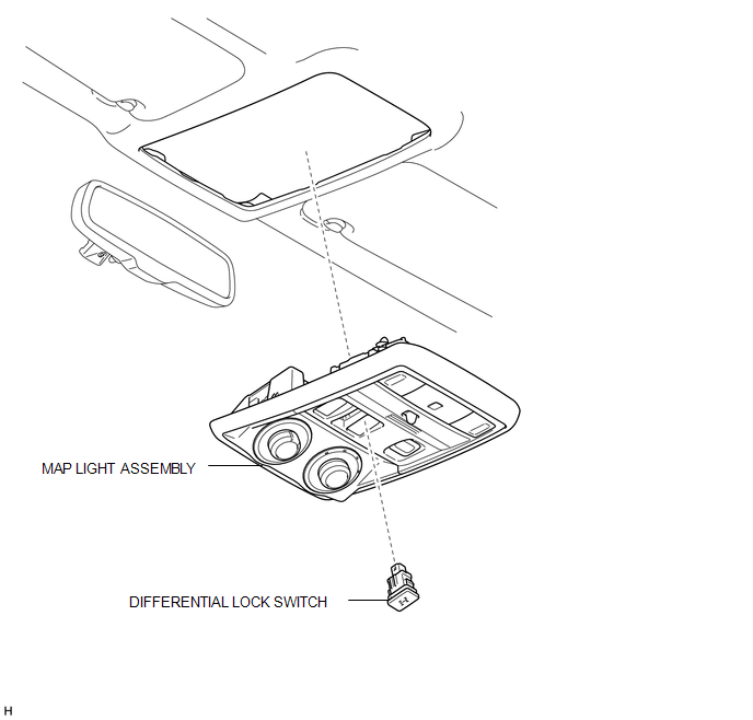
COMPONENTS
ILLUSTRATION
Inspection
INSPECTION
PROCEDURE
1. INSPECT DIFFERENTIAL LOCK SWITCH
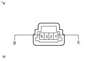
(a) Measure the resistance according to the value(s) in the table below.
Standard Resistance:
|
Tester Connection |
Switch Condition |
Specified Condition |
|---|---|---|
|
1 (E) - 4 (B) |
Pressed |
Below 1 Ω |
|
Not pressed |
100 kΩ or higher |
|
*a |
Component without harness connected (Differential Lock Switch) |
If the result is not as specified, replace the differential lock switch.
Removal
REMOVAL
PROCEDURE
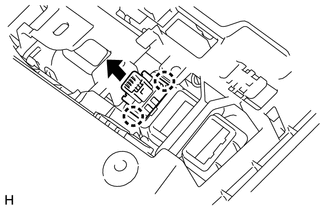
1. REMOVE MAP LIGHT ASSEMBLY
.gif)
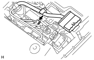
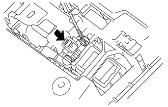
2. REMOVE DIFFERENTIAL LOCK SWITCH
|
(a) Disconnect the differential lock switch connector. |
|
|
(b) Using a screwdriver, detach the 2 claws and remove the differential lock switch from the map light assembly. HINT: Tape the screwdriver tip before use. |
|
Installation
INSTALLATION
PROCEDURE
1. INSTALL DIFFERENTIAL LOCK SWITCH
|
(a) Attach the 2 claws to install the differential lock switch to the map light assembly. |
|
(b) Connect the connector.
2. INSTALL MAP LIGHT ASSEMBLY
.gif)
 Replacement
REPLACEMENT
PROCEDURE
1. REMOVE REAR PROPELLER SHAFT ASSEMBLY
(a) for 2WD:
Remove the rear propeller shaft assembly (See page
).
(b) for 4WD:
Remove the rear propeller shaft assembly (See page ...
 Rear Differential Lock Position Switch
Components
COMPONENTS
ILLUSTRATION
Inspection
INSPECTION
PROCEDURE
1. INSPECT REAR DIFFERENTIAL LOCK POSITION SWITCH
(a) Measure the resistance according to the value(s) in the ...
Other materials about Toyota 4Runner:
Accessory Meter
Components
COMPONENTS
ILLUSTRATION
Removal
REMOVAL
PROCEDURE
1. DISCONNECT CABLE FROM NEGATIVE BATTERY TERMINAL
CAUTION:
Wait at least 90 seconds after disconnecting the cable from the negative (-)
battery terminal to disable the SRS system.
N ...
Reassembly
REASSEMBLY
PROCEDURE
1. INSTALL STEERING RACK END SUB-ASSEMBLY
(a) Temporarily install the 2 steering rack ends to the steering rack.
(b) Fill up the ball joints of the steering rack ends with MP grease.
(c) Using SST, install the steering rack ...

0.0069