Toyota 4Runner: Rear Lateral Control Rod
Components
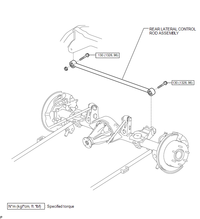
COMPONENTS
ILLUSTRATION
Removal
REMOVAL
PROCEDURE
1. REMOVE REAR LATERAL CONTROL ROD ASSEMBLY
|
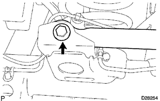
(a) Remove the bolt. |
|
|
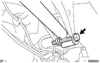
(b) Remove the bolt, nut and lateral control rod assembly. HINT: Turn the bolt while holding the nut. |
|
Installation
INSTALLATION
PROCEDURE
1. TEMPORARILY INSTALL REAR LATERAL CONTROL ROD ASSEMBLY
(a) Temporarily install the lateral control rod assembly with the bolt and nut.
(b) Temporarily tighten the bolt.
2. STABILIZE SUSPENSION
.gif)
3. TIGHTEN REAR LATERAL CONTROL ROD ASSEMBLY
|
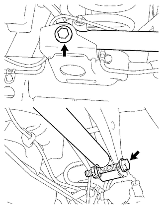
(a) Tighten the 2 bolts. Torque: 130 N·m {1326 kgf·cm, 96 ft·lbf} HINT: Turn the bolt while holding the nut. |
|
 Rear Coil Spring
Components
COMPONENTS
ILLUSTRATION
Removal
REMOVAL
CAUTION / NOTICE / HINT
HINT:
Use the same procedure for the RH and LH sides.
The procedure listed below is for the LH side. ...
 Rear Lower Arm
Components
COMPONENTS
ILLUSTRATION
Removal
REMOVAL
CAUTION / NOTICE / HINT
HINT:
Use the same procedure for the RH and LH sides.
The procedure listed below is for the LH side. ...
Other materials about Toyota 4Runner:
Engine Speed Signal Error (Test Mode DTC) (C2194/94)
DESCRIPTION
The tire pressure warning ECU receives an engine speed signal from the ECM. This
DTC is stored upon entering test mode and cleared when an engine speed signal of
1000 rpm is detected for 3 seconds or more. This DTC is stored only in test mode. ...
Removal
REMOVAL
PROCEDURE
1. REMOVE JACK BOX HOLE COVER
2. REMOVE REAR QUARTER PANEL MUDGUARD LH
3. REMOVE REAR QUARTER PANEL MUDGUARD RH
HINT:
Use the same procedure as for the LH side.
4. REMOVE REAR BUMPER COVER
5. REMOVE NO. 3 FLOOR WIRE
6. RE ...

0.0251