Toyota 4Runner: Rear No. 1 Seat Inner Belt Assembly(for 60/40 Split Double-folding Seat Type Rh Side)
Components
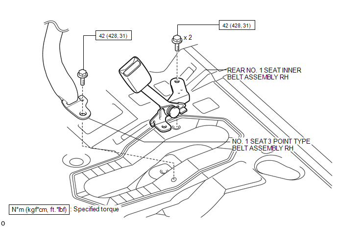
COMPONENTS
ILLUSTRATION
Removal
REMOVAL
PROCEDURE
1. DISCONNECT REAR NO. 1 SEAT OUTER BELT ASSEMBLY RH
|
(a) Pull the rear seat cushion band, release the lock and lift up the back of the seat cushion to rotate it forward. |
|

|
(b) Remove the bolt and disconnect the outer belt floor anchor. |
|

2. REMOVE REAR NO. 1 SEAT INNER BELT ASSEMBLY RH
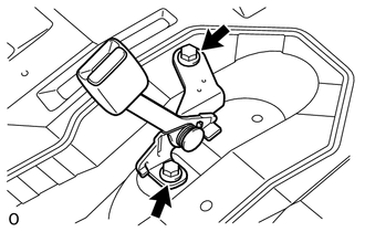
(a) Remove the 2 bolts and inner belt.
Installation
INSTALLATION
PROCEDURE
1. INSTALL REAR NO. 1 SEAT INNER BELT ASSEMBLY RH
(a) Install the inner belt with the 2 bolts.
Torque:
42 N·m {428 kgf·cm, 31 ft·lbf}
2. CONNECT REAR NO. 1 SEAT OUTER BELT ASSEMBLY RH
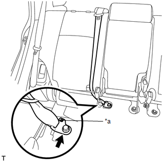
(a) Connect the outer belt floor anchor with the bolt.
Torque:
42 N·m {428 kgf·cm, 31 ft·lbf}
NOTICE:
The anchor part of the seat belt must not overlap the protruding part.
Text in Illustration|
*a |
Protruding Part |
(b) Return the seat cushion to its original position.
 Rear No. 1 Seat Inner Belt Assembly(for 60/40 Split Double-folding Seat Type
Lh Side)
Rear No. 1 Seat Inner Belt Assembly(for 60/40 Split Double-folding Seat Type
Lh Side)
Components
COMPONENTS
ILLUSTRATION
Installation
INSTALLATION
PROCEDURE
1. INSTALL REAR NO. 1 SEAT INNER BELT ASSEMBLY LH
(a) Install the inner belt with the bolt.
Torque:
42 N·m {428 ...

Other materials about Toyota 4Runner:
Removal
REMOVAL
CAUTION / NOTICE / HINT
HINT:
Use the same procedure for the RH and LH sides.
The procedure listed below is for the LH side.
PROCEDURE
1. REMOVE ROOF HEADLINING ASSEMBLY
(a) Remove the roof headlining assembly (See page
).
2. ...
Data List / Active Test
DATA LIST / ACTIVE TEST
1. DATA LIST
NOTICE:
In the table below, the values listed under "Normal Condition" are reference
values. Do not depend solely on these reference values when deciding whether a part
is faulty or not.
HINT:
Using the T ...

0.0077