Toyota 4Runner: Rear No. 2 Seat Inner Belt Assembly
Components
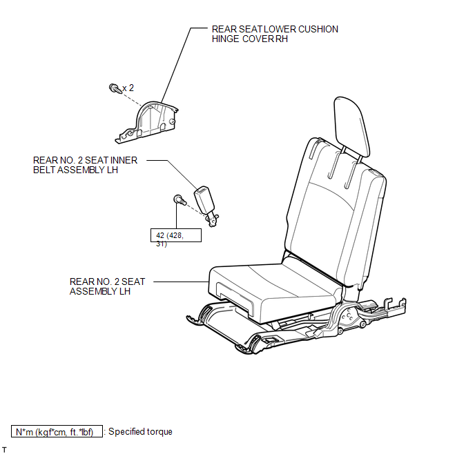
COMPONENTS
ILLUSTRATION
Installation
INSTALLATION
CAUTION / NOTICE / HINT
HINT:
A bolt without a torque specification is shown in the standard bolt chart (See
page .gif) ).
).
PROCEDURE
1. INSTALL REAR NO. 2 SEAT INNER BELT SUB-ASSEMBLY
(a) Using a T45 "TORX" socket wrench, install the inner belt assembly with the bolt.
Torque:
42 N·m {428 kgf·cm, 31 ft·lbf}
2. INSTALL REAR SEAT LOWER CUSHION HINGE COVER RH
3. INSTALL REAR NO. 2 SEAT ASSEMBLY LH
(a) Install the rear No. 2 seat assembly LH (See page
).
Removal
REMOVAL
CAUTION / NOTICE / HINT
CAUTION:
Wear protective gloves. Sharp areas on the parts may injure your hands.
HINT:
- Use the same procedure for the RH and LH sides.
- The procedure listed below is for the LH side.
PROCEDURE
1. REMOVE REAR NO. 2 SEAT ASSEMBLY LH
(a) Remove the rear No. 2 seat assembly LH (See page
.gif) ).
).
2. REMOVE REAR SEAT LOWER CUSHION HINGE COVER RH
3. REMOVE REAR NO. 2 SEAT INNER BELT ASSEMBLY LH
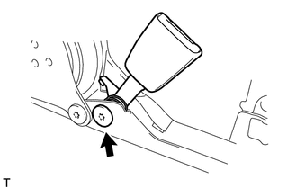
(a) Using a T45 "TORX" socket wrench, remove the bolt and inner belt assembly.
 Installation
INSTALLATION
CAUTION / NOTICE / HINT
HINT:
Use the same procedure for the RH and LH sides.
The procedure listed below is for the LH side.
A bolt without a torque specification is sh ...

Other materials about Toyota 4Runner:
Removal
REMOVAL
CAUTION / NOTICE / HINT
CAUTION:
Wear protective gloves. Sharp areas on the parts may injure your hands.
HINT:
Use the same procedure for the RH and LH sides.
The procedure listed below is for the LH side.
PROCEDURE
1. REMOVE D ...
Gauges and meters
Non-Optitron type meters
Optitron type meters
1. Tachometer Displays the engine speed in revolutions per minute
2. Speedometer Displays the vehicle speed
3. Display change button
4. Engine coolant temperature gauge Displays the engine coolant tempe ...

0.0262