Toyota 4Runner: Reassembly
REASSEMBLY
CAUTION / NOTICE / HINT
NOTICE:
When installing parts, coat the parts indicated by arrows with power steering
fluid (See page .gif) ).
).
PROCEDURE
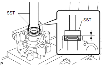
1. INSTALL VANE PUMP HOUSING OIL SEAL
(a) Coat the lip of a new vane pump housing oil seal with MP grease.
|
(b) Using SST and a press, press in the oil seal. SST: 09950-60010 09951-00280 SST: 09950-70010 09951-07100 NOTICE: Make sure that the oil seal is installed facing in the correct direction as shown in the illustration. |
|
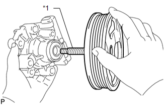
2. INSTALL VANE PUMP SHAFT WITH VANE PUMP PULLEY
(a) Coat the inside surface of the bushing in the vane pump front housing with power steering fluid.
|
(b) Gradually insert the vane pump shaft with vane pump pulley. Text in Illustration
NOTICE:
|
|
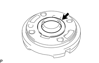
3. INSTALL VANE PUMP FRONT SIDE PLATE
|
(a) Coat a new O-ring with power steering fluid and install it to the vane pump front housing. |
|
|
(b) Coat a new O-ring with power steering fluid and install it to the front side plate. |
|
|
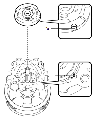
(c) Align the notch of the front side plate with the notch of the vane pump front housing and install the front side plate. Text in Illustration
NOTICE: Make sure that the front side plate is installed facing in the correct direction. |
|
4. INSTALL VANE PUMP CAM RING
|
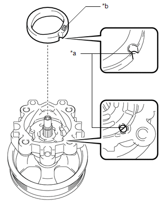
(a) Align the notch of the cam ring with the notch of the front side plate and install the cam ring with the inscribed mark facing upward. Text in Illustration
NOTICE: Make sure that the cam ring is installed facing in the correct direction. |
|
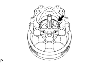
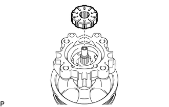
5. INSTALL VANE PUMP ROTOR
|
(a) Install the vane pump rotor. HINT: The vane pump rotor can be installed with either side facing up. |
|
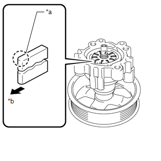
(b) Coat the 10 vane pump plates with power steering fluid.
|
(c) Install the vane pump plates with the round end facing outward. Text in Illustration
NOTICE: Make sure that the vane pump plates are installed facing in the correct direction. |
|
6. INSTALL VANE PUMP SHAFT SNAP RING
(a) Using a screwdriver and snap ring expander, install a new shaft snap ring to the vane pump shaft.
NOTICE:
- Do not expand the shaft snap ring any further than needed.
- Make sure that the shaft snap ring fits completely into the groove.
- Do not damage the vane pump rotor and shaft.
7. INSTALL VANE PUMP REAR HOUSING
|
(a) Coat a new O-ring with power steering fluid and install it to the rear housing. |
|
|
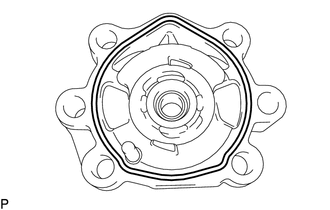
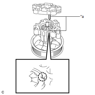
(b) Align the straight pin of the rear housing with the notches of the cam ring, front side plate and vane pump front housing. Text in Illustration
NOTICE: Make sure that the O-ring is not protruding from anywhere when installing the vane pump rear housing. |
|
(c) Install the rear housing with the 4 bolts.
Torque:
22 N·m {224 kgf·cm, 16 ft·lbf}
8. SECURE VANE PUMP ASSEMBLY
9. INSPECT TOTAL PRELOAD
(a) Check that the pump rotates smoothly without abnormal noise.
(b) Temporarily install a service bolt.
Recommended Service Bolt:
|
Item |
Value |
|---|---|
|
Thread diameter |
10 mm (0.394 in.) |
|
Thread pitch |
1.25 mm (0.0492 in.) |
|
Bolt length |
50 mm (1.97 in.) |
|
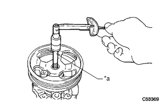
(c) Using a torque wrench, measure the pump rotating torque. Text in Illustration
Standard rotating torque: 0.3 N*m (3 kgf*cm, 2 in.*lbf) or less If the rotating torque is not as specified, check the vane pump housing oil seal. |
|
10. INSTALL SUCTION PORT UNION
(a) Coat a new O-ring with power steering fluid and install it to the suction port union.
(b) Install the suction port union to the vane pump with the bolt.
Torque:
12 N·m {122 kgf·cm, 9 ft·lbf}
 Inspection
INSPECTION
PROCEDURE
1. INSPECT VANE PUMP SHAFT AND BUSH IN VANE PUMP FRONT HOUSING
(a) Using a micrometer, measure the outer diameter of the vane pump shaft.
Text in Illustration
...
 Installation
INSTALLATION
PROCEDURE
1. INSTALL VANE PUMP ASSEMBLY
(a) Install the vane pump with the 2 bolts.
Torque:
43 N·m {438 kgf·cm, 32 ft·lbf}
(b) Install the wire harness bracket with the bolt.
T ...
Other materials about Toyota 4Runner:
Removal
REMOVAL
PROCEDURE
1. DISCONNECT CABLE FROM NEGATIVE BATTERY TERMINAL
CAUTION:
Wait at least 90 seconds after disconnecting the cable from the negative (-)
battery terminal to disable the SRS system.
NOTICE:
When disconnecting the cable, some systems ne ...
Dtc Check / Clear
DTC CHECK / CLEAR
1. CHECK DTC
(a) Connect the Techstream to the DLC3.
(b) Turn the ignition switch to ON and turn the Techstream on.
(c) Enter the following menus: Body Electrical / Trouble Codes.
(d) Check for DTCs.
2. CLEAR DTC
(a) Connect the Techst ...

0.026