Toyota 4Runner: Reassembly
REASSEMBLY
PROCEDURE
1. INSTALL FRONT DRIVE SHAFT DUST COVER
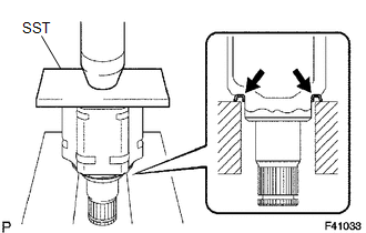
(a) Using SST and a press, install a new dust cover.
SST: 09527-10011
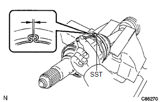
2. INSTALL SHAFT SNAP RING
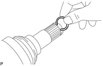
(a) Install a new snap ring.
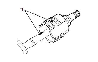
3. INSTALL OUTBOARD JOINT BOOT
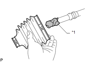
HINT:
Before installing the boot, wrap vinyl tape around the spline of the shaft to prevent damage to the boot.
Text in Illustration|
*1 |
Vinyl Tape |
(a) Temporarily install a new outboard joint boot with 2 new clamps to the outboard joint shaft.
(b) Pack the outboard joint and boot with grease from the boot kit.
Standard grease capacity:
266 to 276 g (9.4 to 9.7 oz.)
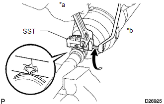
4. INSTALL FRONT NO. 2 AXLE OUTBOARD JOINT BOOT CLAMP
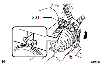
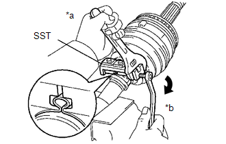
(a) Place SST to the front No. 2 axle outboard joint boot clamp.
SST: 09521-24010
Text in Illustration|
*a |
Hold |
|
*b |
Turn |
(b) Tighten SST so that the No. 2 front axle outboard joint boot clamp is pinched.
NOTICE:
Do not overtighten SST.
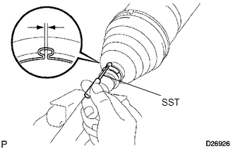
|
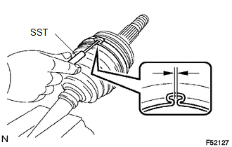
(c) Using SST, measure the clearance of the No. 2 front axle out board joint boot clamp. SST: 09240-00020 Standard Clearance: 2.1 mm (0.0827 in.) or less CAUTION: If the measured value is more than the specified value, retighten the clamp. |
|
5. INSTALL FRONT NO. 1 AXLE OUTBOARD JOINT BOOT CLAMP
(a) Hold the drive shaft lightly in a vise between aluminum plates.
NOTICE:
Do not overtighten the vise.
(b) Secure the outboard joint boot clamp onto the boot.
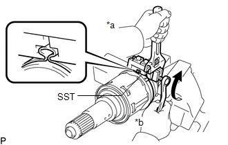
|
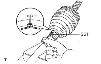
(c) Place SST onto the outboard joint boot clamp. SST: 09521-24010 Text in Illustration
|
|
(d) Tighten SST so that the front axle outboard joint boot clamp is pinched.
NOTICE:
Do not overtighten SST.
|
(e) Using SST, measure the clearance of the front axle outboard joint boot clamp. SST: 09240-00020 Clearance: 1.3 mm (0.0512 in.) or less NOTICE: If the measured value is more than the specified value, retighten the clamp. |
|
6. INSTALL INBOARD JOINT BOOT
(a) Temporarily install a new inboard joint boot to the outboard joint shaft.
7. INSTALL FRONT AXLE INBOARD JOINT SHAFT
(a) Install new parts to the outboard joint shaft in the following order.
|
1. |
Front axle inboard joint boot clamp |
|
2. |
Front axle inboard joint boot |
|
3. |
Front No. 2 axle inboard joint boot clamp |
(b) Fix the outboard joint shaft in a vise between aluminum plates.
NOTICE:
Do not overtighten the vise.
|
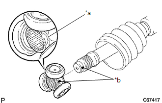
(c) Align the matchmarks and install the tripod joint onto the outboard joint shaft. NOTICE: Place the beveled side of the tripod toward the inboard joint. Text in Illustration
|
|
(d) Align the matchmarks and install the tripod to the inboard joint.
(e) Using a brass bar and hammer, tap the tripod onto the drive shaft.
NOTICE:
- Do not hit the roller portion.
- Keep the tripod joint free of foreign matter.
|
(f) Using a snap ring expander, install a new snap ring. |
|
.png)
(g) Pack the inboard joint assembly and boot with grease from the boot kit.
Standard Grease capacity:
239 to 249 g (8.4 to 8.7 oz.)
|
(h) Align the matchmarks and install the inboard joint onto the outboard joint shaft. Text in Illustration
|
|
8. INSTALL FRONT NO. 1 AXLE INBOARD JOINT BOOT CLAMP
(a) Hold the drive shaft lightly in a vise between aluminum plates.
NOTICE:
Do not overtighten the vise.
(b) Secure the inboard joint boot clamp onto the boot.
|
(c) Place SST onto the inboard joint boot clamp. SST: 09521-24010 Text in Illustration
|
|
(d) Tighten SST so that the front axle inboard joint boot clamp is pinched.
NOTICE:
Do not overtighten SST.
|
(e) Using SST, measure the clearance of the front axle inboard joint boot clamp. SST: 09240-00020 Clearance: 1.3 mm (0.0512 in.) or less NOTICE: If the measured value is greater than the specified value, retighten the clamp. |
|
9. INSTALL FRONT NO. 2 AXLE INBOARD JOINT BOOT CLAMP
(a) Hold the inboard joint shaft assembly in a vise between aluminium plates.
NOTICE:
Do not overtighten the vise.
|
(b) Place SST onto the No. 2 front axle inboard joint boot clamp. SST: 09521-24010 Text in Illustration
|
|
(c) Tighten SST so that the No. 2 front axle inboard joint boot clamp is pinched.
NOTICE:
Do not overtighten SST.
|
(d) Using SST, measure the clearance of the No. 2 front axle inboard joint boot clamp. SST: 09240-00020 Clearance: 2.1 mm (0.0827 in.) or less NOTICE: If the measured value is greater than the specified value, retighten the clamp. |
|
 Installation
INSTALLATION
PROCEDURE
1. INSTALL FRONT DRIVE SHAFT ASSEMBLY
(a) Coat the spline of the inboard joint shaft assembly with ATF.
(b) Align the shaft splines and install the drive shaft with a bras ...

Other materials about Toyota 4Runner:
Hall Effect Sensor LH Pulse (41,42)
DESCRIPTION
When there is noise present in the side auto step motor hall pulse signal, the
side auto step controller ECU assembly halts the operation of the automatic running
board.
DTC No.
Detection Condition
Trouble Are ...
Mechanical System Tests
MECHANICAL SYSTEM TESTS
1. STALL SPEED TEST
HINT:
This test is to check the overall performance of the engine and transmission.
CAUTION:
To ensure safety, perform this test in an open and level area that provides
good traction.
The stall s ...

0.0079