Toyota 4Runner: Reassembly
REASSEMBLY
PROCEDURE
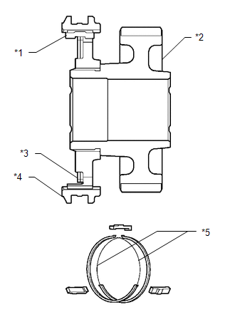
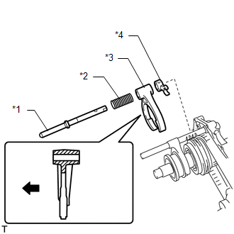
1. INSTALL TRANSFER DRIVE SPROCKET SUB-ASSEMBLY
 Text in Illustration
|
*1 |
Shifting Key |
|
*2 |
Drive Sprocket |
|
*3 |
Key Spring |
|
*4 |
Clutch Sleeve |
|
*5 |
Key Spring Opening |
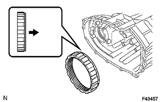
(a) Apply gear oil to the connecting areas of the clutch sleeve and drive sprocket.
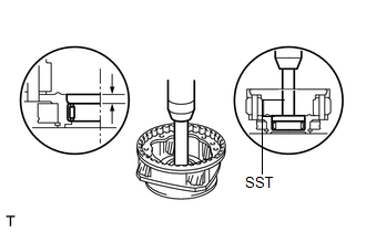
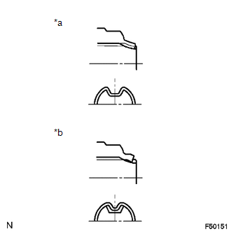
(b) Install the clutch sleeve and 3 shifting keys to the drive sprocket with the 2 shifting key springs.
NOTICE:
- Install the clutch sleeve in the correct direction.
- Install the key springs so that their openings do not overlap as shown in the illustration.
- Make sure that the key springs are firmly connected to the shifting keys.
- Make sure that the clutch sleeve and drive sprocket move smoothly.
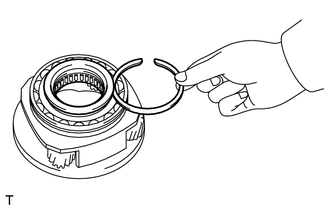
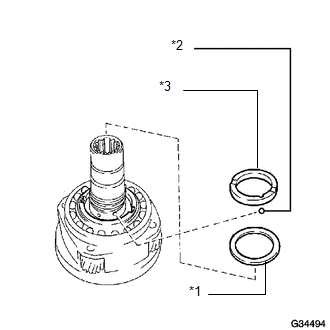
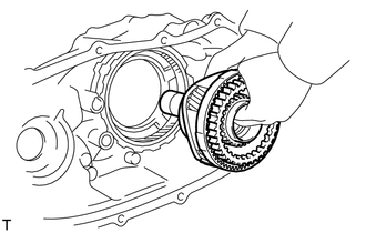
(c) Apply gear oil to the front drive synchronizer ring taper cone side.
|
(d) Install the front drive synchronizer ring. Text in Illustration
|
|
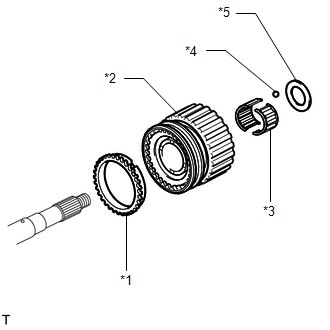
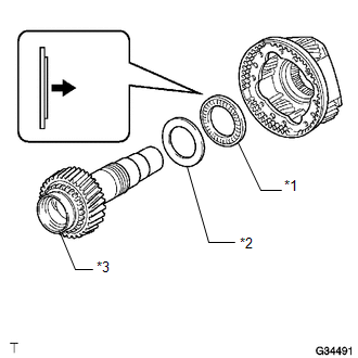
(e) Apply gear oil to the output shaft and needle roller bearing.
(f) Install the needle roller bearing to the drive sprocket.
(g) Install the drive sprocket (with clutch sleeve).
(h) Install the ball. Then install the spacer so that the spacer is aligned with the ball.
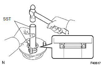
2. INSTALL REAR TRANSFER OUTPUT SHAFT RADIAL BALL BEARING
(a) Apply gear oil to the connecting areas of the output shaft and bearing.
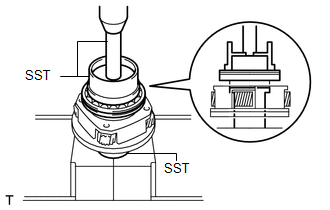
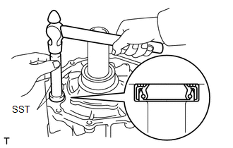
(b) Using SST and a press, press in a new bearing with the outer race snap ring groove facing toward the rear.
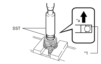
SST: 09316-60011
09316-00011
09316-00071
Text in Illustration|
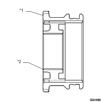
*1 |
Groove |
.png) |
Rear |
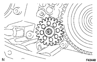
3. CHECK TRANSFER DRIVE SPROCKET THRUST CLEARANCE
.png)
(a) Using a feeler gauge, measure the thrust clearance.
Standard thrust clearance:
0.10 to 0.25 mm (0.00394 to 0.00984 in.)
Maximum thrust clearance:
0.25 mm (0.00984 in.)
If the thrust clearance is more than the maximum, replace the drive sprocket.
4. INSTALL TRANSFER CLUTCH HUB
(a) Apply gear oil to the connecting areas of the clutch sleeve and clutch hub.
|
(b) Install the clutch sleeve to the clutch hub. Text in Illustration
NOTICE:
|
|
(c) Apply gear oil to the connecting areas of the clutch sleeve and output shaft.
|
(d) Using a press, press in the clutch hub. |
|

5. INSTALL TRANSFER OUTPUT SHAFT SNAP RING

(a) Select a new snap ring that allows the minimum axial free play.
Standard Snap Ring Thickness:
|
Mark |
Specified Condition |
|---|---|
|
K |
2.00 to 2.05 mm (0.0787 to 0.0807 in.) |
|
L |
2.05 to 2.10 mm (0.0807 to 0.0827 in.) |
|
A |
2.10 to 2.15 mm (0.0827 to 0.0846 in.) |
|
B |
2.15 to 2.20 mm (0.0846 to 0.0866 in.) |
|
C |
2.20 to 2.25 mm (0.0866 to 0.0886 in.) |
|
D |
2.25 to 2.30 mm (0.0886 to 0.0906 in.) |
|
E |
2.30 to 2.35 mm (0.0906 to 0.0925 in.) |
|
F |
2.35 to 2.40 mm (0.0925 to 0.0945 in.) |
|
G |
2.40 to 2.45 mm (0.0945 to 0.0965 in.) |
|
H |
2.45 to 2.50 mm (0.0965 to 0.0984 in.) |
|
J |
2.50 to 2.55 mm (0.0984 to 0.1004 in.) |
(b) Using a snap ring expander, install the snap ring.
NOTICE:
Make sure that the snap ring is firmly installed to the groove.
6. INSTALL TRANSFER LOW PLANETARY GEAR BEARING
(a) Using SST and a press, press in a new bearing.
SST: 09950-60010
09951-00570
SST: 09950-70010
09951-00710
Standard depth:
7.7 to 8.3 mm (0.303 to 0.327 in.)
7. INSTALL TRANSFER INPUT SHAFT BEARING
(a) Using SST and a press, press in a new bearing with the groove facing forward.
SST: 09223-15020
SST: 09515-30010
SST: 09950-70010
09951-07100
8. INSTALL TRANSFER INPUT BEARING SHAFT SNAP RING
(a) Select a new snap ring that allows 0.1 mm (0.00394 in.) or less of axial free play.
Standard Snap Ring Thickness:
|
Mark |
Specified Condition |
|---|---|
|
1 |
1.45 to 1.50 mm (0.0571 to 0.0591 in.) |
|
2 |
1.50 to 1.55 mm (o.0591 to 0.0610 in.) |
|
3 |
1.55 to 1.60 mm (0.0610 to 0.0630 in.) |
|
4 |
1.60 to 1.65 mm (0.0630 to 0.0650 in.) |
|
5 |
1.65 to 1.70 mm (0.0650 to 0.0669 in.) |
(b) Using a snap ring expander, install the snap ring.
NOTICE:
Make sure that the snap ring is firmly installed to the groove.
9. INSTALL NO. 1 TRANSFER INPUT SHAFT SEAL RING

(a) Apply gear oil to 2 new seal rings.
(b) Install the 2 seal rings to the input shaft.
NOTICE:
When installing the seal ring, make sure not to expand it so that its inner diameter exceeds 65 mm (2.56 in.).
10. INSTALL TRANSFER LOW PLANETARY GEAR BEARING
(a) Install the bearing to the low planetary gear.
 Text in Illustration
|
*1 |
Low Planetary Gear Bearing |
|
*2 |
No. 1 Thrust Bearing Race |
|
*3 |
Input Shaft |
|
|
Front |
NOTICE:
Install the bearing in the correct direction.
11. INSTALL NO. 1 TRANSFER THRUST BEARING RACE
(a) Install the bearing race to the low planetary gear.
12. INSTALL TRANSFER INPUT SHAFT
(a) Apply gear oil to the contact surfaces of the input shaft and low planetary gear.
(b) Install the input shaft to the low planetary gear.
13. INSTALL MANUAL TRANSFER PLANETARY CARRIER WASHER
 Text in Illustration
|
*1 |
Planetary Carrier Washer |
|
*2 |
Input Gear Stopper Ball |
|
*3 |
Input Gear Stopper |
(a) Apply gear oil to the washer.
(b) Install the washer to the low planetary gear.
14. INSTALL TRANSFER INPUT GEAR STOPPER BALL
(a) Install the ball to the low planetary gear.
15. INSTALL TRANSFER INPUT GEAR STOPPER
(a) Install the stopper to the low planetary gear.
16. INSTALL TRANSFER INPUT GEAR STOPPER SHAFT SNAP RING
(a) Select a new snap ring that allows 0.05 to 0.15 mm (0.00196 to 0.00590 in.) of axial free play.
Standard Snap Ring Thickness:
|
Mark |
Specified Condition |
|---|---|
|
A |
2.10 to 2.15 mm (0.0827 to 0.0846 in.) |
|
B |
2.15 to 2.20 mm (0.0846 to 0.0866 in.) |
|
C |
2.20 to 2.25 mm (0.0866 to 0.0886 in.) |
|
D |
2.25 to 2.30 mm (0.0886 to 0.0906 in.) |
|
E |
2.30 to 2.35 mm (0.0906 to 0.0925 in.) |
|
F |
2.35 to 2.40 mm (0.0925 to 0.0945 in.) |
|
G |
2.40 to 2.45 mm (0.0945 to 0.0965 in.) |
|
H |
2.45 to 2.50 mm (0.0965 to 0.0984 in.) |
|
J |
2.50 to 2.55 mm (0.0984 to 0.1004 in.) |
|
K |
2.55 to 2.60 mm (0.1004 to 0.1024 in.) |
|
L |
2.60 to 2.65 mm (0.1024 to 0.1043 in.) |
|
M |
2.65 to 2.70 mm (0.1043 to 0.1063 in.) |
|
N |
2.70 to 2.75 mm (0.1063 to 0.1083 in.) |
|
P |
2.75 to 2.80 mm (0.1083 to 0.1102 in.) |
|
Q |
2.80 to 2.85 mm (0.1102 to 0.1122 in.) |
|
R |
2.85 to 2.90 mm (0.1122 to 0.1142 in.) |
|
S |
2.90 to 2.95 mm (0.1142 to 0.1161 in.) |
|
T |
2.95 to 3.00 mm (0.1161 to 0.1181 in.) |
|
U |
3.00 to 3.05 mm (0.1181 to 0.1201 in.) |
(b) Using a snap ring expander, install the snap ring.
NOTICE:
Make sure that the snap ring is firmly installed to the groove.
17. INSTALL FRONT TRANSFER OUTPUT SHAFT NEEDLE ROLLER BEARING
(a) Apply gear oil to the bearing.
(b) Install the bearing to the low planetary gear.
18. INSTALL TRANSFER LOW PLANETARY GEAR SPLINE PIECE
(a) Install the gear spline piece to the low planetary gear.
|
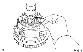
(b) Using a screwdriver, install the snap ring. NOTICE: Be careful not to damage the gear spline piece. |
|
.png)
19. INSTALL TRANSFER CASE OIL SEAL
|
(a) Using SST and a hammer, tap in 2 new oil seals until their surfaces are flush with the case upper surface. SST: 09950-60010 09951-00230 SST: 09950-70010 09951-07100 Oil seal depth: -0.5 to 0.5 mm (-0.0197 to 0.0197 in.) NOTICE: Be careful not to damage the front case. |
|
(b) Coat the lip of the seal with MP grease.
20. INSTALL TRANSFER LOW PLANETARY RING GEAR
(a) Install the ring gear to the front transfer case.
Text in Illustration|
|
Front |
NOTICE:
Install the ring gear in the correct direction.
|
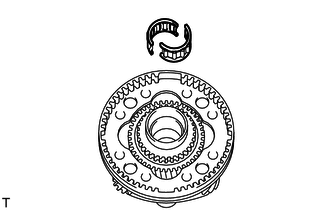
(b) Using a screwdriver, install the snap ring. NOTICE: Make sure that the snap ring is firmly installed to the groove. |
|
.png)
21. INSTALL PIN
|
(a) Install the pin. Text in Illustration
|
|
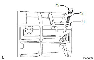
22. INSTALL COMPRESSION SPRING
(a) Install the spring.
23. INSTALL TRANSFER CASE PLUG
(a) Apply adhesive to the threads of the plug.
Adhesive:
Toyota Genuine Adhesive 1344, Three Bond 1344 or equivalent
(b) Install the plug.
Torque:
19 N·m {190 kgf·cm, 14 ft·lbf}
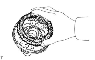
24. INSTALL TRANSFER LOW PLANETARY GEAR ASSEMBLY WITH TRANSFER INPUT SHAFT
(a) Install the low planetary gear together with the input shaft.
HINT:
If necessary, heat the front case to between approximately 50 and 80°C (122 and 176°F).
|
(b) Using a snap ring expander, install the snap ring. NOTICE: Make sure that the snap ring is firmly installed to the groove. |
|
.png)
25. INSTALL TRANSFER OIL PUMP GEAR
(a) Apply gear oil to the sliding surface of the oil pump gear.
(b) Install the oil pump gear.
26. INSTALL TRANSFER OIL PUMP BODY O-RING
(a) Coat a new O-ring with gear oil and install it to the pump body.
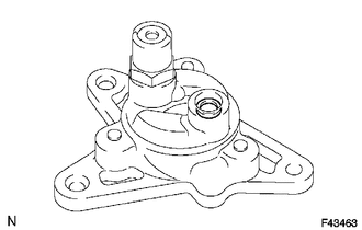
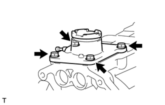
27. INSTALL TRANSFER OIL PUMP BODY SUB-ASSEMBLY

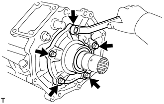
(a) Install the oil pump body with the 3 bolts.
Torque:
7.5 N·m {76 kgf·cm, 66 in·lbf}
28. INSTALL TRANSFER CASE MAGNET
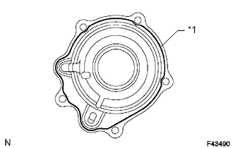
29. INSTALL TRANSFER OIL SEPARATOR SUB-ASSEMBLY
.png)
(a) Install the oil separator with the 3 bolts.
Torque:
7.5 N·m {76 kgf·cm, 66 in·lbf}
30. INSTALL FILLER PLUG
(a) Install a new gasket and the filler plug.
Torque:
37 N·m {377 kgf·cm, 27 ft·lbf}
31. INSTALL DRAIN PLUG
(a) Install a new gasket and the drain plug.
Torque:
37 N·m {377 kgf·cm, 27 ft·lbf}
32. INSTALL TRANSFER INPUT GEAR RADIAL BALL BEARING
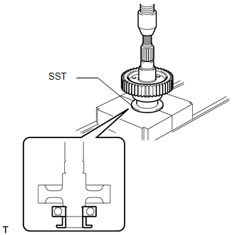
(a) Apply gear oil to the contact surfaces of the bearing and driven sprocket.
(b) Using SST and a press, press in a new bearing.
SST: 09316-60011
09316-00031
NOTICE:
After press-fitting the bearing to the driven sprocket, check that the bearing moves smoothly.
33. INSTALL TRANSFER DRIVEN SPROCKET BEARING

(a) Apply gear oil to the contact surfaces of the bearing and driven sprocket.
(b) Using SST and a press, press in a new bearing.
SST: 09316-60011
09316-00071
NOTICE:
After press-fitting the bearing to the driven sprocket, check that the bearing moves smoothly.
34. INSTALL REAR TRANSFER OUTPUT SHAFT, FRONT TRANSFER DRIVE CHAIN AND TRANSFER DRIVEN SPROCKET
.png)
(a) Mount the rear transfer case in a vise.
Text in Illustration|
*1 |
Aluminum Plate |
NOTICE:
Place aluminum plates on the vise to prevent damage to the rear transfer case.
(b) Install the output shaft and driven sprocket to the drive chain.
(c) Install the output shaft, drive chain and driven sprocket to the rear transfer case.
NOTICE:
When installing the output shaft, make sure that the installation of the synchronizer ring, sleeve and shifting keys is not affected.
HINT:
Check that the output shaft and driven sprocket turn smoothly.
If necessary, heat the rear transfer case to between approximately 50 and 80°C (122 and 176°F).
|
(d) Using a snap ring expander, install the snap ring. NOTICE: Make sure that the snap ring is firmly installed to the groove. |
|
.png)
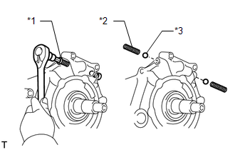
35. INSTALL TRANSFER HIGH AND LOW SHIFT FORK SHAFT
(a) Apply gear oil to the connecting areas of the shift fork shaft and each part.
(b) Install the shift fork shaft and No. 2 gear shift fork.
Text in Illustration|
*1 |
Shift Fork Shaft |
|
*2 |
No. 2 Gear Shift Fork |
NOTICE:
Install the shift fork shaft and No. 2 gear shift fork in the correct directions.
(c) Install the spring and ball to the hole.
(d) Apply adhesive to the threads of the plug.
Adhesive:
Toyota Genuine Adhesive 1344, Three Bond 1344 or equivalent
(e) Using a hexagon wrench, install the plug.
Torque:
19 N·m {190 kgf·cm, 14 ft·lbf}
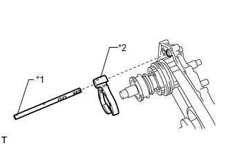
36. INSTALL FRONT TRANSFER DRIVE SHIFT FORK SHAFT

(a) Apply gear oil to the straight pin.
(b) Install the straight pin to the hole.
(c) Apply gear oil to the connecting areas of the shift fork shaft and each part.
(d) Install the shift fork shaft, No. 1 gear shift fork, spring and shift shaft stopper.
 Text in Illustration
|
*1 |
Shift Fork Shaft |
|
*2 |
Spring |
|
*3 |
No. 1 Gear Shift Fork |
|
*4 |
Shift Shaft Stopper |
|
|
Front |
NOTICE:
Install the shift fork shaft, No. 1 gear shift fork and shift shaft stopper in the correct directions.
|
(e) Using a pin punch and hammer, install the 2 slotted pins. NOTICE: When installing the slotted pins, make sure that groove A of the pin is facing in the same direction as the shaft. |
|

|
(f) Install the spring and ball to the hole. Text in Illustration
|
|
(g) Apply adhesive to the threads of the plug.
Adhesive:
Toyota Genuine Adhesive 1344, Three Bond 1344 or equivalent
(h) Using a hexagon wrench, install the plug.
Torque:
19 N·m {190 kgf·cm, 14 ft·lbf}
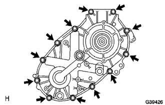
37. INSTALL REAR TRANSFER CASE

(a) Apply seal packing to the rear transfer case as shown in the illustration.
Seal packing:
Toyota Genuine Seal Packing 1281, Three Bond 1281 or equivalent
Text in Illustration|
*1 |
Seal Packing |
NOTICE:
If the removed rear transfer case will be reused, be sure to perform the following before reinstalling it: 1) using a knife, cut off any old seal packing on the rear transfer case contact surface, 2) clean off any remaining old seal packing from the rear transfer case contact surface, and 3) reapply seal packing to the rear transfer case.
|
(b) Install the clamp and rear case with the 12 bolts. Torque: 28 N·m {286 kgf·cm, 21 ft·lbf} NOTICE: Tighten the bolts of the rear transfer case within 10 minutes of applying the seal packing. The seal packing will dry very quickly. |
|
38. INSTALL TRANSFER SPEEDOMETER DRIVE GEAR
(a) Install the speedometer drive gear and ball.
39. INSTALL TRANSFER OUTPUT SHAFT WASHER
(a) Install the 2 output washers.
40. INSTALL TRANSFER EXTENSION HOUSING SUB-ASSEMBLY

(a) Apply seal packing to the extension housing as shown in the illustration.
Seal packing:
Toyota Genuine Seal Packing 1281, Three Bond 1281 or equivalent
Text in Illustration|
*1 |
Seal Packing |
NOTICE:
If the removed extension housing will be reused, be sure to perform the following before reinstalling it: 1) using a knife, cut off any old seal packing on the housing contact surface, 2) clean off any remaining old seal packing from the housing contact surface, and 3) reapply seal packing to the housing.
(b) Apply adhesive to the threads of the bolts.
Adhesive:
Toyota Genuine Adhesive 1344, Three Bond 1344 or equivalent
(c) Install the extension housing with the 5 bolts.
Torque:
12 N·m {122 kgf·cm, 9 ft·lbf}
NOTICE:
Tighten the bolts of the extension housing within 10 minutes of applying the seal packing. The seal packing will dry very quickly.
41. INSTALL SPEEDOMETER DRIVEN HOLE COVER SUB-ASSEMBLY
(a) Install a new O-ring and the speedometer driven hole cover sub-assembly with the bolt.
Torque:
12 N·m {117 kgf·cm, 8 ft·lbf}
42. INSTALL TRANSFER CASE FRONT OIL SEAL
.gif)
43. INSTALL FRONT TRANSFER OUTPUT SHAFT COMPANION FLANGE OIL SEAL
(a) Using SST and a hammer, tap in a new oil seal.
SST: 09950-60010
09951-00320
SST: 09950-70010
09951-07100
NOTICE:
Be careful not to damage the companion flange.
44. INSTALL FRONT OUTPUT SHAFT COMPANION FLANGE SUB-ASSEMBLY

(a) Apply gear oil to the connecting areas of the companion flange and driven sprocket.
(b) Install the companion flange to the driven sprocket.
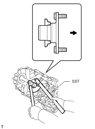
(c) Using SST to hold the companion flange, install a new lock nut.
SST: 09330-00021
Torque:
118 N·m {1203 kgf·cm, 87 ft·lbf}
|
(d) Using a chisel and hammer, stake the lock nut to the driven sprocket. Text in Illustration
NOTICE:
|
|
45. INSTALL TRANSFER CASE REAR OIL SEAL
46. INSTALL REAR TRANSFER OUTPUT SHAFT COMPANION FLANGE OIL SEAL
(a) Using SST and a hammer, tap in a new oil seal.
SST: 09950-60010
09951-00320
SST: 09950-70010
09951-07100
NOTICE:
Be careful not to damage the companion flange.
47. INSTALL REAR OUTPUT SHAFT COMPANION FLANGE SUB-ASSEMBLY
(a) Apply gear oil to the connecting areas of the companion flange and output shaft.
(b) Install the companion flange to the output shaft.
(c) Using SST to hold the companion flange, install a new lock nut.
SST: 09330-00021
Torque:
118 N·m {1203 kgf·cm, 87 ft·lbf}
|
(d) Using a chisel and hammer, stake the lock nut. Text in Illustration
NOTICE:
|
|

48. INSTALL TRANSFER BEARING RETAINER OIL SEAL

(a) Using SST and a hammer, tap in a new oil seal until its surface is flush with the bearing retainer upper surface.
SST: 09950-60010
09951-00590
SST: 09950-70010
09951-07100
NOTICE:
Be careful not to damage the bearing retainer.
(b) Coat the lip of the oil seal with MP grease.
49. INSTALL TRANSFER BEARING RETAINER SUB-ASSEMBLY
(a) Apply seal packing to the bearing retainer as shown in the illustration.
Seal packing:
Toyota Genuine Seal Packing 1281, Three Bond 1281 or equivalent
Text in Illustration|
*1 |
Seal Packing |
NOTICE:
If the removed bearing retainer will be reused, be sure to perform the following before reinstalling it: 1) using a knife, cut off any old seal packing on the retainer contact surface, 2) clean off any remaining old seal packing from the retainer contact surface, and 3) reapply seal packing to the retainer.
(b) Apply sealant to the bolt threads.
Adhesive:
Toyota Genuine Adhesive 1344, Three Bond 1344 or equivalent
|
(c) Install the retainer with the 5 bolts. Torque: 12 N·m {117 kgf·cm, 8 ft·lbf} NOTICE: Tighten the bolts of the bearing retainer within 10 minutes of applying the seal packing. The seal packing will dry very quickly. |
|
50. INSTALL BREATHER OIL DEFLECTOR
(a) Install the breather oil deflector.
51. INSTALL TRANSFER CONTROL SHIFT LEVER RETAINER SUB-ASSEMBLY
(a) Install the retainer with the 4 bolts.
Torque:
18 N·m {184 kgf·cm, 13 ft·lbf}
52. INSTALL TRANSFER INDICATOR SWITCH (4WD POSITION)
53. INSTALL TRANSFER INDICATOR SWITCH (L4 POSITION)
54. INSTALL TRANSFER INDICATOR SWITCH (NEUTRAL POSITION)
 Inspection
INSPECTION
PROCEDURE
1. INSPECT TRANSFER INPUT SHAFT
(a) Using a micrometer, measure the diameter of the input shaft journal.
Minimum diameter:
47.59 mm (1.88 in.)
If the diameter is less tha ...
 Installation
INSTALLATION
PROCEDURE
1. INSTALL TRANSFER ASSEMBLY
(a) Install the transfer to the transmission.
(b) Install the 8 bolts.
Torque:
24 N·m {245 kgf·cm, 18 ft·lbf}
2. INSTALL AUTOMATIC TRANSM ...
Other materials about Toyota 4Runner:
System Description
SYSTEM DESCRIPTION
1. FRONT POWER SEAT CONTROL SYSTEM DESCRIPTION
The driver seat is equipped with slide, reclining, lifter, front vertical
and lumbar support adjustment functions.
The passenger seat is equipped with slide and reclining adjust ...
System Description
SYSTEM DESCRIPTION
1. TOUCH SWITCH OUTLINE
Touch switches are touch-sensitive (interactive) switches operated by touching
the screen. When a switch is pressed, the outer film bends in to contact the inner
glass at the pressed position. By doing this, the ...

0.0128