Toyota 4Runner: Removal
REMOVAL
PROCEDURE
1. DISCONNECT CABLE FROM NEGATIVE BATTERY TERMINAL
CAUTION:
Wait at least 90 seconds after disconnecting the cable from the negative (-) battery terminal to disable the SRS system.
NOTICE:
When disconnecting the cable, some systems need to be initialized after the cable
is reconnected (See page .gif) ).
).
2. REMOVE DOOR SCUFF PLATE ASSEMBLY RH
|
(a) Put protective tape around the door scuff plate. Text in Illustration
|
|
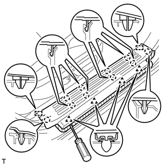
(b) Using a screwdriver, detach the 4 clips, 10 claws and 2 guides and remove the door scuff plate.
HINT:
Tape the screwdriver tip before use.
3. REMOVE COWL SIDE TRIM BOARD RH
|
(a) Remove the clip. |
|
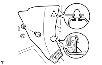
(b) Detach the clip and claw and remove the cowl side trim board.
4. REMOVE NO. 2 INSTRUMENT CLUSTER FINISH PANEL GARNISH
HINT:
Use the same procedure described for the No. 1 instrument cluster finish panel garnish.
(a) Remove the No. 2 instrument cluster finish panel garnish (See page
).
5. REMOVE NO. 2 INSTRUMENT PANEL UNDER COVER SUB-ASSEMBLY
6. REMOVE LOWER INSTRUMENT COVER LH
7. REMOVE LOWER NO. 2 INSTRUMENT PANEL AIRBAG ASSEMBLY
8. REMOVE INSTRUMENT PANEL BOX DOOR COVER
9. REMOVE LOWER INSTRUMENT PANEL SUB-ASSEMBLY
10. REMOVE NO. 2 AIR DUCT SUB-ASSEMBLY
11. REMOVE ECU INTEGRATION BOX RH
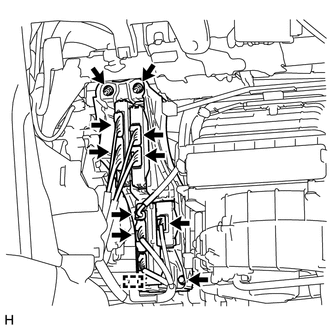
(a) Disconnect all the connectors.
(b) Detach the clamp.
(c) Remove the 2 nuts, bolt and ECU integration box RH.
12. REMOVE POWER MANAGEMENT CONTROL ECU
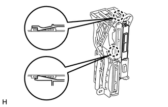
(a) Detach the 2 claws and remove the power management control ECU.
 Components
COMPONENTS
ILLUSTRATION
...
 Installation
INSTALLATION
CAUTION / NOTICE / HINT
HINT:
A bolt without a torque specification is shown in the standard bolt chart (See
page ).
PROCEDURE
1. INSTALL POWER MANAGEMENT CONTROL ECU
(a) Attach ...
Other materials about Toyota 4Runner:
Reverse Signal Circuit
DESCRIPTION
The radio and display receiver assembly receives a reverse signal from the park/neutral
position switch assembly.
WIRING DIAGRAM
PROCEDURE
1.
CHECK HARNESS AND CONNECTOR (REVERSE SIGNAL)
(a) Disconnect the G ...
If the engine will not start
If the engine will not start even though correct starting procedures are
being followed (, 173), consider each of the following points:
The engine will not start even though the starter motor operates normally.
One of the following may be the cause of the ...

0.0261