Toyota 4Runner: Removal
REMOVAL
CAUTION / NOTICE / HINT
HINT:
- Use the same procedure for the RH and LH sides.
- The procedure listed below is for the LH side.
PROCEDURE
1. REMOVE FRONT WHEEL
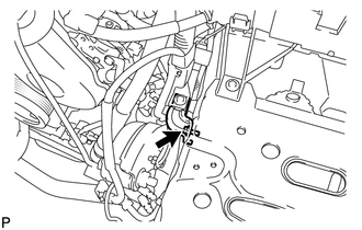
2. REMOVE SKID CONTROL SENSOR WIRE
.gif)
3. REMOVE FRONT SUSPENSION UPPER ARM ASSEMBLY LH
|
(a) Support the front suspension lower arm LH with a jack. |
|
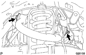
(b) Remove the clip and nut.
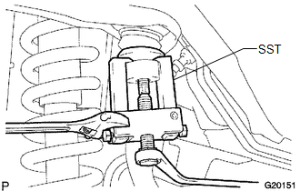
(c) Using SST, disconnect the upper ball joint from the steering knuckle.
SST: 09628-62011
|
(d) Remove the bolt and disconnect the bracket. |
|
|
(e) Remove the bolt, 2 washers and nut. |
|
(f) Remove the front suspension upper arm assembly.
 Disassembly
DISASSEMBLY
PROCEDURE
1. REMOVE FRONT SUSPENSION UPPER ARM BUSH LH
HINT:
Use the same procedure for the front and rear sides.
(a) Using a hammer and chisel, strike and bend the entire ...
 Inspection
INSPECTION
PROCEDURE
1. INSPECT FRONT SUSPENSION UPPER ARM ASSEMBLY LH
(a) As shown in the illustration, flip the ball joint stud back and forth
5 times before installing the nut.
...
Other materials about Toyota 4Runner:
Backup Battery Degradation (B15EC)
DESCRIPTION
This DTC is stored when the DCM (Telematics Transceiver) detects either of the
following conditions.
The BUB (Back-Up Battery) charge level becomes less than the criteria.
Automatic Collision Notification (ACN) was performed.
...
Crawl Indicator Light Remains ON
DESCRIPTION
Refer to Crawl Indicator Light does not Come ON (See page
).
WIRING DIAGRAM
Refer to Crawl Indicator Light does not Come ON (See page
).
CAUTION / NOTICE / HINT
NOTICE:
When replacing the master cylinder solenoid, perform calibration (See ...

0.0197