Toyota 4Runner: Removal
REMOVAL
PROCEDURE
1. REMOVE UPPER RADIATOR SUPPORT SEAL
.gif)
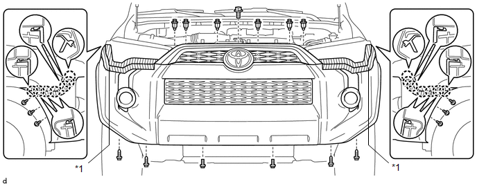
2. REMOVE FRONT BUMPER COVER
(a) Put protective tape around the front bumper cover.
(b) Remove the 3 bolts, 10 screws and 6 clips.
(c) Detach the 14 claws to remove the front bumper cover with radiator grille.
 Text in Illustration
|
*1 |
Protective Tape |
- |
- |
(d) Disconnect the 2 connectors.
3. REMOVE UPPER CENTER FRONT BUMPER RETAINER
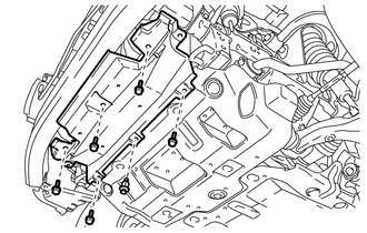
4. REMOVE FRONT BUMPER LOWER COVER
|
(a) Remove the clip, 5 bolts and front lower bumper cover. |
|
5. REMOVE RADIATOR SIDE DEFLECTOR LH
6. REMOVE RADIATOR SIDE DEFLECTOR RH
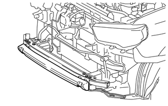
7. REMOVE FRONT BUMPER ENERGY ABSORBER
|
(a) Remove the front bumper energy absorber. |
|
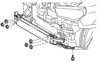
8. REMOVE FRONT BUMPER REINFORCEMENT SUB-ASSEMBLY
|
(a) Remove the 6 nuts, screw and front bumper reinforcement sub-assembly. |
|
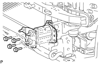
9. REMOVE NO. 2 FRONT BUMPER EXTENSION SUB-ASSEMBLY LH
|
(a) Remove the 4 bolts and No. 2 front bumper extension sub-assembly LH. |
|
10. REMOVE NO. 2 FRONT BUMPER EXTENSION SUB-ASSEMBLY RH
HINT:
Use the same procedure as for the LH side.
11. REMOVE FRONT BUMPER SIDE SUPPORT LH
|
(a) Remove the bolt and screw. |
|
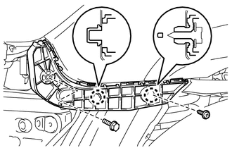
(b) Detach the 2 claws to remove the front bumper side support LH.
12. REMOVE FRONT BUMPER SIDE SUPPORT RH
HINT:
Use the same procedure as for the LH side.
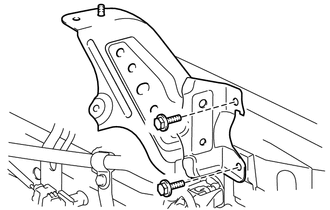
13. REMOVE FRONT BUMPER BRACKET SUB-ASSEMBLY LH
|
(a) Remove the 2 bolts and front bumper bracket sub-assembly LH. |
|
14. REMOVE FRONT BUMPER BRACKET SUB-ASSEMBLY RH
HINT:
Use the same procedure as for the LH side.
 Components
COMPONENTS
ILLUSTRATION
ILLUSTRATION
ILLUSTRATION
...
 Disassembly
DISASSEMBLY
PROCEDURE
1. REMOVE RADIATOR GRILLE
2. REMOVE FRONT BUMPER EXTENSION MOUNTING BRACKET (w/ License Plate Bracket)
(a) Remove the 2 screws to remove the front bumper extens ...
Other materials about Toyota 4Runner:
Party mode switch
Party mode switch You can switch the sounds quality types by pressing the
switch.
1. Base mode
2. Party mode
In party mode, the sound volume from the speakers on the back door is bigger
than in base mode.
(The output from the speakers on the rear do ...
System Description
SYSTEM DESCRIPTION
1. DESCRIPTION
(a) In the Variable Flow Control (VFC) power steering system, the power steering
ECU assembly receives the steering angle signal, steering zero point memory, the
steering speed, vehicle speed signal and engine speed sign ...

0.009