Toyota 4Runner: Removal
REMOVAL
PROCEDURE
1. REMOVE REAR NO. 1 SPOILER COVER
(a) Detach the 4 clips and remove the rear No. 1 spoiler cover.
2. REMOVE REAR SPOILER SUB-ASSEMBLY
|
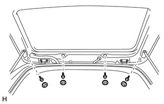
(a) Remove the 4 grommets and 4 bolts. |
|
|
(b) Put protective tape around the rear spoiler. Text in Illustration
|
|
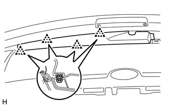
(c) Disconnect the connector.
(d) Detach the 3 claws and remove the rear spoiler.
3. REMOVE REAR NO. 2 SPOILER CLIP
HINT:
Use the same procedure to remove the rear No. 2 spoiler clip on the other side.
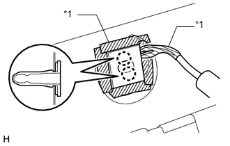
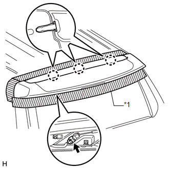
(a) Put protective tape around the No. 2 rear spoiler clip.
(b) Detach the 2 claws and No. 2 rear spoiler clip.
Text in Illustration|
*1 |
Protective Tape |
 Components
COMPONENTS
ILLUSTRATION
ILLUSTRATION
...
 Disassembly
DISASSEMBLY
PROCEDURE
1. REMOVE REAR NO. 1 SPOILER PROTECTOR
(a) Remove the rear No. 1 spoiler protector.
2. REMOVE REAR NO. 2 SPOILER PROTECTOR
HINT:
Use the same procedure to remove the rear ...
Other materials about Toyota 4Runner:
Installation
INSTALLATION
PROCEDURE
1. INSTALL REAR DIFFERENTIAL CARRIER ASSEMBLY
(a) Install a new gasket and the differential carrier assembly with the 10 nuts
and 10 washers.
Torque:
52 N·m {530 kgf·cm, 38 ft·lbf}
2. INSTALL REAR AXLE SHAFT LH
(a) Install t ...
Microphone Circuit between Microphone and Radio Receiver
DESCRIPTION
The radio and display receiver assembly and map light assembly (telephone
microphone assembly) are connected to each other using the microphone connection
detection signal lines.
Using this circuit, the radio and display receive ...

0.0303