Toyota 4Runner: Removal
REMOVAL
PROCEDURE
1. REMOVE GENERATOR ASSEMBLY
(a) Remove the generator assembly (See page .gif)
).
2. RECOVER REFRIGERANT FROM REFRIGERATION SYSTEM
3. DISCONNECT DISCHARGE HOSE SUB-ASSEMBLY
|
(a) Remove the bolt and disconnect the discharge hose from the cooler compressor. |
|
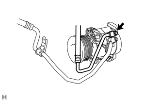
(b) Remove the O-ring from the discharge hose.
NOTICE:
Seal the openings of the disconnected parts using vinyl tape to prevent moisture and foreign matter from entering them.
4. DISCONNECT SUCTION HOSE SUB-ASSEMBLY
|
(a) Remove the 2 bolts and disconnect the suction hose from the cooler compressor. |
|
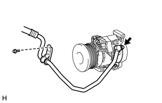
(b) Remove the O-ring from the suction hose.
NOTICE:
Seal the openings of the disconnected parts using vinyl tape to prevent moisture and foreign matter from entering them.
5. REMOVE COOLER COMPRESSOR ASSEMBLY
|
(a) Disconnect the connector. |
|
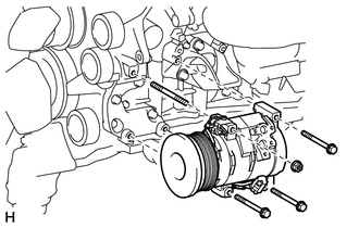
(b) Remove the 3 bolts and nut.
(c) Remove the stud bolt and cooler compressor.
 Inspection
INSPECTION
PROCEDURE
1. INSPECT MAGNET CLUTCH ASSEMBLY
(a) Check the magnet clutch operation.
(1) Confirm that the magnet clutch hub and magnet clutch rotor lock when the
positive (+) lead of ...
 Installation
INSTALLATION
PROCEDURE
1. ADJUST COMPRESSOR OIL
(a) When replacing the compressor and magnetic clutch with a new one, gradually
discharge the refrigerant gas from the service valve and drain the ...
Other materials about Toyota 4Runner:
Removal
REMOVAL
PROCEDURE
1. DISCONNECT CABLE FROM NEGATIVE BATTERY TERMINAL
CAUTION:
Wait at least 90 seconds after disconnecting the cable from the negative (-)
battery terminal to disable the SRS system.
NOTICE:
When disconnecting the cable, some systems ne ...
Differential Oil
Replacement
REPLACEMENT
PROCEDURE
1. INSPECT DIFFERENTIAL OIL LEVEL
(a) Stop the vehicle on a level surface.
(b) Remove the differential filler plug and gasket.
(c) Check that the oil level is within 0 to 5 mm (0 to 0.197 in.) of
the bot ...

0.026