Toyota 4Runner: Removal
REMOVAL
PROCEDURE
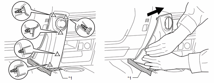
1. REMOVE NO. 1 INSTRUMENT CLUSTER FINISH PANEL GARNISH
(a) Put protective tape around the No. 1 instrument cluster finish panel garnish.
(b) Grip the No. 1 instrument cluster finish panel garnish and pull it diagonally upward toward the rear to detach the 5 clips and remove the No. 1 instrument cluster finish panel garnish.
 Text in Illustration
|
*1 |
Protective Tape |
- |
- |
2. REMOVE NO. 2 INSTRUMENT CLUSTER FINISH PANEL GARNISH
.gif)
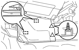
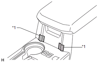
3. REMOVE FRONT NO. 1 CONSOLE BOX INSERT
|
(a) Detach the 2 clips and 2 guides to remove the front No. 1 console box insert. |
|
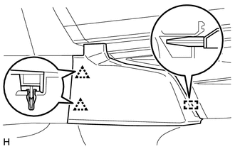
4. REMOVE FRONT NO. 2 CONSOLE BOX INSERT
|
(a) Detach the 2 clips and guide to remove the front No. 2 console box insert. |
|
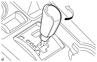
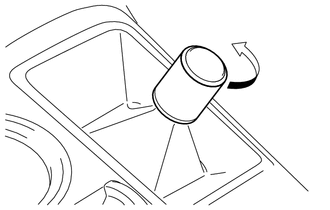
5. REMOVE SHIFT LEVER KNOB SUB-ASSEMBLY
|
(a) Turn the shift lever knob sub-assembly in the direction indicated by the arrow and remove it. |
|
6. REMOVE SHIFT LEVER KNOB SUB-ASSEMBLY (for VF2A)
|
(a) Turn the shift lever knob sub-assembly in the direction indicated by the arrow and remove it. |
|
7. REMOVE UPPER CONSOLE PANEL SUB-ASSEMBLY
|
(a) Put protective tape around the upper console panel sub-assembly. Text in Illustration
|
|
(b) Using a moulding remover, detach the 10 clips.
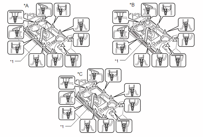 Text in Illustration
|
*A |
for VF2A |
*B |
for VF2BM, VF4BM |
|
*C |
for 2WD |
- |
- |
|
*1 |
Protective Tape |
- |
- |
(c) Disconnect each connector and remove the upper console panel sub-assembly.
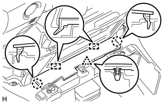
8. REMOVE NO. 2 CONSOLE BOX RETAINER
|
(a) Detach the clip, 2 claws and 2 guides to remove the No. 2 console box retainer. |
|
9. REMOVE REAR CONSOLE BOX ASSEMBLY
|
(a) Remove the 4 bolts and 2 screws. |
|
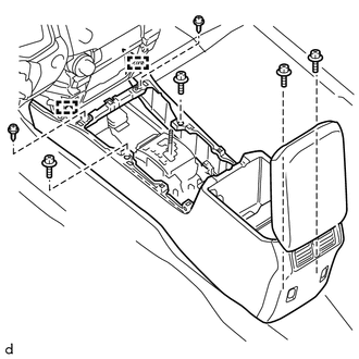
(b) Detach the 2 guides.
(c) Disconnect each connector and remove the rear console box assembly.
 Disassembly
DISASSEMBLY
PROCEDURE
1. REMOVE NO. 1 POWER OUTLET SOCKET ASSEMBLY
2. REMOVE NO. 1 POWER OUTLET SOCKET COVER
3. REMOVE REAR CONSOLE END PANEL
(a) Detach the 4 clips and 4 claws t ...
 Installation
INSTALLATION
CAUTION / NOTICE / HINT
HINT:
A bolt without a torque specification is shown in the standard bolt chart (See
page ).
PROCEDURE
1. INSTALL REAR CONSOLE BOX ASSEMBLY
(a) Connect ea ...
Other materials about Toyota 4Runner:
IG Power Source Circuit
DESCRIPTION
When the ignition switch is turned to ON, the IG power source circuit supplies
positive (+) voltage to the power steering ECU assembly.
WIRING DIAGRAM
CAUTION / NOTICE / HINT
NOTICE:
Inspect the fuses for circuits related to this system be ...
Installation
INSTALLATION
CAUTION / NOTICE / HINT
HINT:
Use the same procedure for the RH and LH sides.
The procedure listed below is for the LH side.
When installing the window frame moulding, black out tape and outside
stripe, heat the vehicle body ...

0.0267