Toyota 4Runner: Removal
REMOVAL
PROCEDURE
1. REMOVE SHIFT LEVER KNOB SUB-ASSEMBLY
.gif)
2. REMOVE SHIFT LEVER KNOB SUB-ASSEMBLY (for VF2A)
3. REMOVE UPPER CONSOLE PANEL SUB-ASSEMBLY
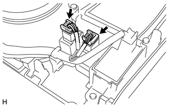
4. REMOVE SEAT HEATER SWITCH
|
(a) Disconnect the 2 connectors. |
|
|
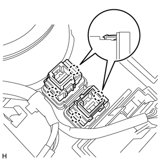
(b) Detach the 4 claws and remove the 2 switches. |
|
 Inspection
INSPECTION
PROCEDURE
1. INSPECT SEAT HEATER SWITCH LH
(a) Measure the resistance according to the value(s) in the table below.
Standard Resistance:
Tester Connection
Sw ...
 Installation
INSTALLATION
PROCEDURE
1. INSTALL SEAT HEATER SWITCH
(a) Attach the 4 claws to install the 2 switches.
(b) Connect the 2 connectors.
2. INSTALL UPPER CONSOLE PANEL SUB-ASSEMBLY
3. INSTALL SHI ...
Other materials about Toyota 4Runner:
Removal
REMOVAL
PROCEDURE
1. DISCONNECT CABLE FROM NEGATIVE BATTERY TERMINAL
CAUTION:
Wait at least 90 seconds after disconnecting the cable from the negative (-)
battery terminal to disable the SRS system.
NOTICE:
When disconnecting the cable, some systems ne ...
System Description
SYSTEM DESCRIPTION
1. DESCRIPTION OF OCCUPANT CLASSIFICATION SYSTEM
(a) GENERAL DESCRIPTION
(1) In the occupant classification system, the occupant classification ECU calculates
the weight of the occupant based on signals from the occupant classification ...

0.0095