Toyota 4Runner: Removal
REMOVAL
PROCEDURE
1. DISCONNECT CABLE FROM NEGATIVE BATTERY TERMINAL
CAUTION:
Wait at least 90 seconds after disconnecting the cable from the negative (-) battery terminal to disable the SRS system.
NOTICE:
When disconnecting the cable, some systems need to be initialized after the cable
is reconnected (See page .gif) ).
).
2. REMOVE NO. 1 INSTRUMENT CLUSTER FINISH PANEL GARNISH
3. REMOVE NO. 2 INSTRUMENT CLUSTER FINISH PANEL GARNISH
4. REMOVE HEATER CONTROL ASSEMBLY
5. REMOVE SHIFT LEVER KNOB SUB-ASSEMBLY
6. REMOVE SHIFT LEVER KNOB SUB-ASSEMBLY (for VF2A)
7. REMOVE UPPER CONSOLE PANEL SUB-ASSEMBLY
8. REMOVE NO. 2 CONSOLE BOX RETAINER
9. REMOVE LOWER CENTER INSTRUMENT CLUSTER FINISH PANEL SUB-ASSEMBLY (w/ Climate Control Seat System)
10. REMOVE LOWER CENTER INSTRUMENT CLUSTER FINISH PANEL SUB-ASSEMBLY (w/o Climate Control Seat System)
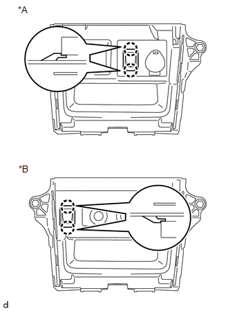
11. REMOVE NO. 1 STEREO JACK ADAPTER ASSEMBLY
|
(a) Detach the 2 claws to remove the No. 1 stereo jack adapter assembly. Text in Illustration
|
|
 Components
COMPONENTS
ILLUSTRATION
ILLUSTRATION
...
 Installation
INSTALLATION
PROCEDURE
1. INSTALL NO. 1 STEREO JACK ADAPTER ASSEMBLY
(a) Attach the 2 claws to install the No. 1 stereo jack adapter assembly.
2. INSTALL LOWER CENTER INSTRUMENT CLUSTER FINISH PAN ...
Other materials about Toyota 4Runner:
Sending Malfunction (Navigation to APGS) (U0073,U0140)
DESCRIPTION
These DTCs are stored when a malfunction occurs in the CAN communication circuit.
DTC No.
DTC Detection Condition
Trouble Area
U0073
CAN bus connection error
CAN communicatio ...
Relay(for Magnet Clutch Control)
On-vehicle Inspection
ON-VEHICLE INSPECTION
PROCEDURE
1. REMOVE MAGNET CLUTCH RELAY
(a) Remove the magnet clutch relay from the engine room relay block.
Text in Illustration
*1
Magnet Clutch Relay
...

0.0089