Toyota 4Runner: Removal
REMOVAL
PROCEDURE
1. DISCONNECT CABLE FROM NEGATIVE BATTERY TERMINAL
CAUTION:
Wait at least 90 seconds after disconnecting the cable from the negative (-) battery terminal to disable the SRS system.
NOTICE:
When disconnecting the cable, some systems need to be initialized after the cable
is reconnected (See page .gif) ).
).
2. REMOVE INSTRUMENT PANEL SUB-ASSEMBLY
(a) Remove the instrument panel sub-assembly (See page
).
3. REMOVE NO. 1 HEATER TO REGISTER DUCT
4. REMOVE NO. 2 HEATER TO REGISTER DUCT
5. REMOVE NO. 1 SIDE DEFROSTER NOZZLE DUCT
6. REMOVE NO. 2 SIDE DEFROSTER NOZZLE DUCT
7. REMOVE NO. 3 HEATER TO REGISTER DUCT
8. REMOVE DEFROSTER NOZZLE ASSEMBLY
9. REMOVE NAVIGATION ANTENNA ASSEMBLY
|
(a) Detach the clamp. |
|
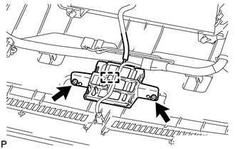
(b) Remove the 2 screws and antenna.
 Components
COMPONENTS
ILLUSTRATION
...
 Inspection
INSPECTION
PROCEDURE
1. INSPECT NAVIGATION ANTENNA ASSEMBLY
(a) Measure the resistance according to the value(s) in the table below.
Standard Resistance:
Tester C ...
Other materials about Toyota 4Runner:
Reassembly
REASSEMBLY
PROCEDURE
1. BEARING POSITION
Bearing and Race Diameter:
Mark
Front Race Diameter Inside/Outside
Thrust Bearing Diameter Inside/Outside
Rear Race Diameter Inside/Outside
A
...
Diagnostic Trouble Code Chart
DIAGNOSTIC TROUBLE CODE CHART
HINT:
If a trouble code is output during the DTC check, inspect the trouble areas listed
for that code. For details of the code, refer to the "See page" below.
Sliding Roof System
DTC Code
Det ...

0.0226