Toyota 4Runner: Removal
REMOVAL
CAUTION / NOTICE / HINT
HINT:
- Use the same procedure for the RH and LH sides.
- The procedure listed below is for the LH side.
PROCEDURE
1. REMOVE FRONT WHEEL
2. REMOVE DISC BRAKE CYLINDER ASSEMBLY LH
.gif)
3. REMOVE FRONT DISC
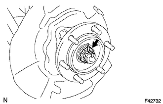
4. REMOVE FRONT AXLE HUB GREASE CAP
(a) Using a screwdriver and hammer, remove the front axle hub grease cap.
NOTICE:
Do not damage the axle hub.
5. REMOVE FRONT AXLE SHAFT NUT
|
(a) Remove the cotter pin and lock cap. |
|
(b) Remove the front axle shaft nut.
6. REMOVE FRONT AXLE HUB SUB-ASSEMBLY LH
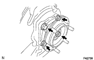
(a) Remove the 4 bolts.
(b) Using a plastic-faced hammer, tap out the front drive shaft from the front axle hub.
NOTICE:
Be careful not to damage the drive shaft boot.
(c) Remove the front axle hub and front disc dust cover.
(d) Remove the O-ring.
 On-vehicle Inspection
ON-VEHICLE INSPECTION
PROCEDURE
1. REMOVE FRONT WHEEL
2. DISCONNECT FRONT DISC BRAKE CYLINDER ASSEMBLY LH
3. REMOVE FRONT DISC
4. REMOVE FRONT AXLE HUB GREASE CAP
5. INSPECT FRONT AXLE ...
 Disassembly
DISASSEMBLY
PROCEDURE
1. REMOVE FRONT AXLE WITH ABS ROTOR BEARING ASSEMBLY LH
(a) Gently fix the front axle hub in a vise between aluminum plates.
...
Other materials about Toyota 4Runner:
Installation with LATCH system (rear/second row seats only)
Installing on the rear seats (vehicles without third row seats)
Fold the seatback while pulling the seatback angle adjustment lever. Return
the seatback and secure it at the first lock position.
Type A
Latch the hooks of the lower straps onto the LATC ...
Data Signal Circuit between Radio Receiver and Extension Module
DESCRIPTION
The stereo component tuner assembly sends the sound data signal or image data
signal from a device to the radio and display receiver assembly via this circuit.
WIRING DIAGRAM
PROCEDURE
1.
CHECK HARNESS AND CONNECTOR ( ...

0.0315