Toyota 4Runner: Room Light(for Front)
Components
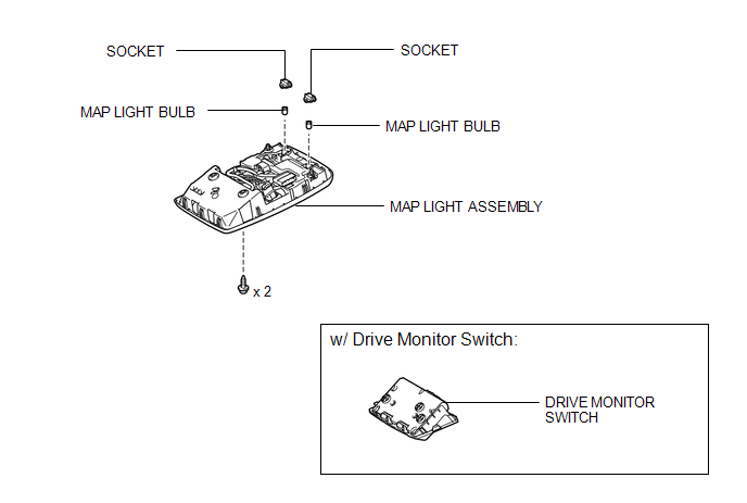
COMPONENTS
ILLUSTRATION
Inspection
INSPECTION
PROCEDURE
1. INSPECT MAP LIGHT ASSEMBLY
|
(a) Measure the resistance according to the value(s) in the table below. Standard Resistance:
|
|
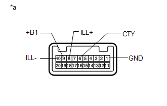
(b) Apply battery voltage to the connector and check the LED illumination.
OK:
|
Condition |
Specified Condition |
|---|---|
|
Battery positive (+) → Terminal 8 (ILL+) Battery negative (-) → Terminal 10 (ILL-) |
LED illuminates |
|
*a |
Component without harness connected (Map Light Assembly) |
If the result is not as specified, replace the map light assembly.
Removal
REMOVAL
PROCEDURE
1. REMOVE DRIVE MONITOR SWITCH (w/ Drive Monitor Switch)
|
(a) Detach the 4 claws to remove the drive monitor switch. |
|
.png)
(b) Disconnect the connector.
2. REMOVE MAP LIGHT ASSEMBLY
(a) Open the cover (w/o Drive Monitor Switch).
|
(b) Remove the 2 screws. |
|
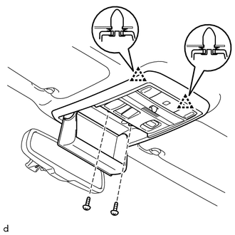
(c) Detach the 2 clips to remove the map light assembly.
(d) Disconnect the connector.
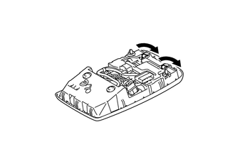
3. REMOVE MAP LIGHT BULB
|
(a) Turn the 2 sockets in the direction indicated by the arrows to remove them. |
|
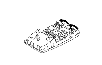
(b) Remove the 2 map light bulbs from the sockets.
Installation
INSTALLATION
PROCEDURE
1. INSTALL MAP LIGHT BULB
(a) Install the 2 map light bulbs to the sockets.
|
(b) Turn the 2 sockets in the direction indicated by the arrows to install them. |
|
2. INSTALL MAP LIGHT ASSEMBLY
(a) Connect the connector.
(b) Attach the 2 clips to install the map light assembly.
(c) Install the 2 screws.
(d) Close the cover (w/o Drive Monitor Switch).
3. INSTALL DRIVE MONITOR SWITCH (w/ Drive Monitor Switch)
(a) Connect the connector.
(b) Attach the 4 claws to install the drive monitor switch.
 Relay
Relay
On-vehicle Inspection
ON-VEHICLE INSPECTION
PROCEDURE
1. INSPECT DOME RELAY
(a) Measure the resistance according to the value(s) in the table below.
Standard Resistance:
...
 Room Light(for Rear)
Components
COMPONENTS
ILLUSTRATION
Installation
INSTALLATION
PROCEDURE
1. INSTALL NO. 1 ROOM LIGHT ASSEMBLY
(a) Align the switch parts as shown in the illustration and attach t ...
Other materials about Toyota 4Runner:
Disassembly
DISASSEMBLY
PROCEDURE
1. REMOVE STEERING LOCK ACTUATOR ASSEMBLY
(a) Using a center punch, mark the center of the tapered-head bolt.
(b) Using a 3 to 4 mm (0.118 to 0.157 in.) drill, drill a hole in the 2 bolts.
(c) Using a screw extractor, remo ...
Mayday Battery
Components
COMPONENTS
ILLUSTRATION
Removal
REMOVAL
PROCEDURE
1. DISCONNECT CABLE FROM NEGATIVE BATTERY TERMINAL
NOTICE:
When disconnecting the cable, some systems need to be initialized after the cable
is reconnected (See page ).
2. REMOVE MA ...

0.0253