Toyota 4Runner: Security Indicator Light Circuit
DESCRIPTION
- When the engine immobiliser system is set, the security indicator light blinks continuously, but does not illuminate if the engine immobiliser system is not set.
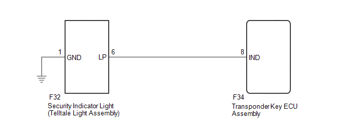
WIRING DIAGRAM
CAUTION / NOTICE / HINT
NOTICE:
When the transponder key ECU assembly is replaced, refer to Registration (See
page .gif) ).
).
PROCEDURE
|
1. |
PERFORM ACTIVE TEST USING TECHSTREAM (SECURITY INDICATOR) |
(a) Check that the security indicator light illuminates when operating it with
the Active Test (See page ).
Immobiliser
|
Tester Display |
Test Part |
Control Range |
Diagnostic Note |
|---|---|---|---|
|
Security Indicator |
Security indicator light |
ON/OFF |
The test is possible when the following conditions are met:
|
OK:
Security indicator light can be turned on and off using the Techstream.
| OK | .gif) |
PROCEED TO NEXT SUSPECTED AREA SHOWN IN PROBLEM SYMPTOMS TABLE |
|
.gif)
|
2. |
INSPECT SECURITY INDICATOR LIGHT (TELLTALE LIGHT ASSEMBLY) |
(a) Remove the security indicator light (telltale light assembly) (See page
).
(b) Inspect the security indicator light (telltale light assembly) (See page
).
| NG | |
REPLACE SECURITY INDICATOR LIGHT (TELLTALE LIGHT ASSEMBLY) |
|
|
3. |
CHECK HARNESS AND CONNECTOR (TELLTALE LIGHT - TRANSPONDER KEY ECU AND BODY GROUND) |
(a) Disconnect the F32 security indicator light (telltale light assembly) connector.
(b) Disconnect the F34 transponder key ECU assembly connector.
(c) Measure the resistance according to the value(s) in the table below.
Standard Resistance:
|
Tester Connection |
Condition |
Specified Condition |
|---|---|---|
|
F32-6 (LP) - F34-8 (IND) |
Always |
Below 1 Ω |
|
F32-1 (GND) - Body ground |
Always |
Below 1 Ω |
|
F32-6 (LP) or F34-8 (IND) - Body ground |
Always |
10 kΩ or higher |
| OK | |
REPLACE TRANSPONDER KEY ECU ASSEMBLY |
| NG | |
REPAIR OR REPLACE HARNESS OR CONNECTOR |
 No Communication in Immobiliser System (B2796,B2798)
DESCRIPTION
DTC B2796 is stored when a key is inserted into the ignition key cylinder
but no communication occurs between the key and transponder key ECU assembly.
DTC B2798 is stor ...
 ECU Power Source Circuit
DESCRIPTION
This circuit provides power to operate the transponder key ECU assembly.
WIRING DIAGRAM
CAUTION / NOTICE / HINT
NOTICE:
Inspect the fuses for circuits related to this system before ...
Other materials about Toyota 4Runner:
System Diagram
SYSTEM DIAGRAM
Communication Table
Sender
Receiver
Signal
Line
Main body ECU (Multiplex network body ECU)
Combination meter assembly
Front door courtesy light switch LH signa ...
Installation
INSTALLATION
PROCEDURE
1. INSTALL STEREO COMPONENT AMPLIFIER ASSEMBLY
(a) Insert the stereo component amplifier to attach the 2 claws.
(b) Install the amplifier with the 3 bolts.
Torque:
2.5 N·m {25 kgf·cm, 22 in·lbf}
(c) Connect the 4 connectors.
...

0.0063