Toyota 4Runner: SFR Solenoid Circuit (C0226,C0236,C0246,C0256,C1225-C1228)
DESCRIPTION
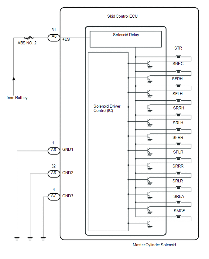
The solenoid turns on when signals are received from the skid control ECU and controls the pressure acting on the wheel cylinders, thus controlling braking force.
|
DTC Code |
DTC Detection Condition |
Trouble Area |
|---|---|---|
|
C0226 |
An open or short circuit in the SFRH or SFRR circuit continues for 0.05 seconds or more. |
|
|
C0236 |
An open or short circuit in the SFLH or SFLR circuit continues for 0.05 seconds or more. |
|
|
C0246 |
An open or short circuit in the SRRH or SRRR circuit continues for 0.05 seconds or more. |
|
|
C0256 |
An open or short circuit in the SRLH or SRLR circuit continues for 0.05 seconds or more. |
|
|
C1225 |
An open or short circuit in the SMCF circuit continues for 0.05 seconds or more. |
|
|
C1226 |
An open or short circuit in the SREA circuit continues for 0.05 seconds or more. |
|
|
C1227 |
An open or short circuit in the SREC circuit continues for 0.05 seconds or more. |
|
|
C1228 |
An open or short circuit in the STR circuit continues for 0.05 seconds or more. |
|
WIRING DIAGRAM
CAUTION / NOTICE / HINT
NOTICE:
When replacing the master cylinder solenoid, perform calibration (See page
.gif) ).
).
PROCEDURE
|
1. |
RECONFIRM DTC |
HINT:
These codes are stored when a problem is detected in the master cylinder solenoid.
The solenoid circuit is in the master cylinder solenoid.
Therefore, solenoid circuit inspections and solenoid unit inspections cannot be performed. Be sure to check if any DTC is output before replacing the master cylinder solenoid.
(a) Clear the DTCs (See page ).
(b) Drive the vehicle at a speed of approximately 32 km/h (20 mph) or more for 60 seconds or more.
(c) Check if the same DTCs are output (See page
).
Result
|
Result |
Proceed to |
|---|---|
|
DTC is output |
A |
|
DTC is not output |
B |
| A | .gif) |
REPLACE MASTER CYLINDER SOLENOID |
| B | |
USE SIMULATION METHOD TO CHECK |
 ABS Control System Malfunction (43)
DESCRIPTION
This DTC is output when the VSC system detects a malfunction in the ABS.
DTC Code
DTC Detection Condition
Trouble Area
43
A m ...
 Open in ABS Solenoid Relay Circuit (C0278,C0279)
DESCRIPTION
The solenoid relay is built into the master cylinder solenoid.
This relay supplies power to each solenoid. If the initial check is OK, after
the ignition switch is turned to ON, the re ...
Other materials about Toyota 4Runner:
Disassembly
DISASSEMBLY
PROCEDURE
1. REMOVE REAR NO. 1 SPOILER PROTECTOR
(a) Remove the rear No. 1 spoiler protector.
2. REMOVE REAR NO. 2 SPOILER PROTECTOR
HINT:
Use the same procedure to remove the rear No. 2 spoiler protector on the other
side.
(a) Remove ...
Removal
REMOVAL
PROCEDURE
1. REMOVE PARK/NEUTRAL POSITION SWITCH ASSEMBLY
(a) Disconnect the switch connector.
(b) Using a screwdriver, bend the tabs of the lock washer.
(c) Remove the lock nut and l ...

0.0091