Toyota 4Runner: Sound Signal Circuit between Navigation Receiver Assembly and Stereo Jack Adapter
DESCRIPTION
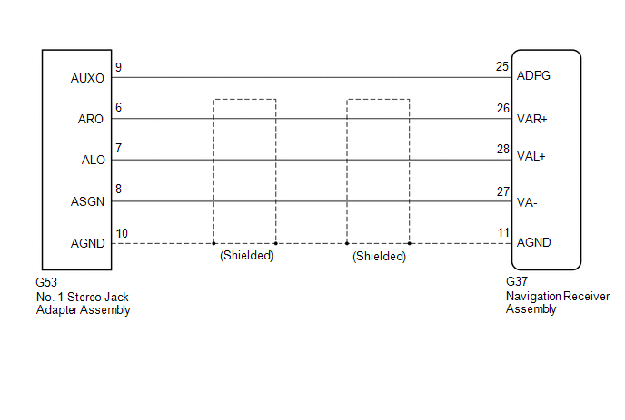
The No. 1 stereo jack adapter assembly sends the sound signal from an external device to the navigation receiver assembly via this circuit.
The sound signal that has been sent is amplified by the stereo component amplifier assembly, and then is sent to the speakers.
If there is an open or short in the circuit, sound cannot be heard from the speakers even if there is no malfunction in the stereo component amplifier assembly, DCM (telematics transceiver)*1 or speakers.
- *1: w/ Manual (SOS) Switch
WIRING DIAGRAM
PROCEDURE
|
1. |
CHECK HARNESS AND CONNECTOR (NAVIGATION RECEIVER ASSEMBLY - NO. 1 STEREO JACK ADAPTER ASSEMBLY) |
|
(a) Disconnect the G37 navigation receiver assembly connector. |
|
(b) Disconnect the G53 No. 1 stereo jack adapter assembly connector.
(c) Measure the resistance according to the value(s) in the table below.
Standard Resistance:
|
Tester Connection |
Condition |
Specified Condition |
|---|---|---|
|
G37-25 (ADPG) - G53-9 (AUXO) |
Always |
Below 1 Ω |
|
G37-26 (VAR+) - G53-6 (ARO) |
Always |
Below 1 Ω |
|
G37-28 (VAL+) - G53-7 (ALO) |
Always |
Below 1 Ω |
|
G37-27 (VA-) - G53-8 (ASGN) |
Always |
Below 1 Ω |
|
G37-11 (AGND) - G53-10 (AGND) |
Always |
Below 1 Ω |
|
G37-25 (ADPG) - Body ground |
Always |
10 kΩ or higher |
|
G37-26 (VAR+) - Body ground |
Always |
10 kΩ or higher |
|
G37-28 (VAL+) - Body ground |
Always |
10 kΩ or higher |
|
G37-27 (VA-) - Body ground |
Always |
10 kΩ or higher |
|
G37-11 (AGND) - Body ground |
Always |
10 kΩ or higher |
|
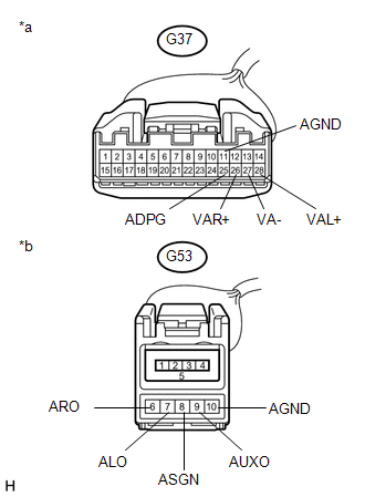
*a |
Front view of wire harness connector (to Navigation Receiver Assembly) |
|
*b |
Front view of wire harness connector (to No. 1 Stereo Jack Adapter Assembly) |
| OK | .gif) |
PROCEED TO NEXT SUSPECTED AREA SHOWN IN PROBLEM SYMPTOMS TABLE |
| NG | |
REPAIR OR REPLACE HARNESS OR CONNECTOR |
 Data Signal Circuit between Navigation Receiver Assembly and Extension Module
DESCRIPTION
The stereo component tuner assembly sends the sound data signal or image data
signal from a device to the navigation receiver assembly via this circuit.
WIRING DIAGRAM
CAUTION / NOT ...
 Data Signal Circuit between Navigation Receiver Assembly and Stereo Jack Adapter
DESCRIPTION
The No. 1 stereo jack adapter assembly sends the sound data signal or image data
signal from a USB device to the navigation receiver assembly via this circuit.
WIRING DIAGRAM
PROCED ...
Other materials about Toyota 4Runner:
Removal
REMOVAL
PROCEDURE
1. DISCONNECT CABLE FROM NEGATIVE BATTERY TERMINAL
NOTICE:
When disconnecting the cable some systems need to be initialized after the cable,
is reconnected (See page ).
2. REMOVE REAR NO. 1 FLOOR STEP COVER (w/ Rear No. 2 Seat)
3. ...
Removal
REMOVAL
PROCEDURE
1. REMOVE SPIRAL CABLE SUB-ASSEMBLY
(a) Remove the spiral cable sub-assembly (See page
).
2. REMOVE WINDSHIELD WIPER SWITCH ASSEMBLY
3. REMOVE HEADLIGHT DIMMER SWITCH ASSEMBLY
(a) Disconnect the connector.
...

0.0153