Toyota 4Runner: Sound Signal Circuit between Radio Receiver and Stereo Jack Adapter
DESCRIPTION
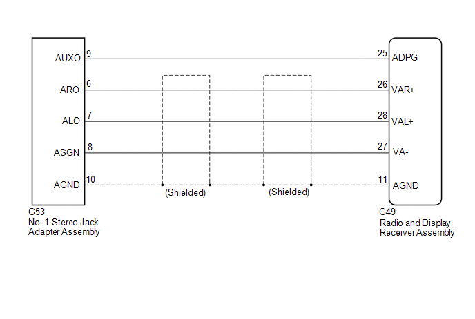
The No. 1 stereo jack adapter assembly sends the sound signal from an external device to the radio and display receiver assembly via this circuit.
The sound signal that has been sent is amplified by the radio and display receiver assembly and then is sent to the speakers.
If there is an open or short in the circuit, sound cannot be heard from the speakers even if there is no malfunction in the radio and display receiver assembly or speakers.
WIRING DIAGRAM
PROCEDURE
|
1. |
CHECK HARNESS AND CONNECTOR (RADIO AND DISPLAY RECEIVER ASSEMBLY - NO. 1 STEREO JACK ADAPTER ASSEMBLY) |
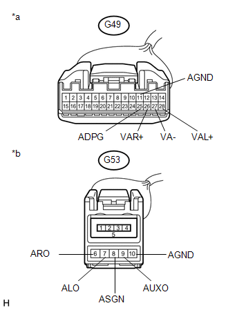
(a) Disconnect the G49 radio and display receiver assembly connector.
(b) Disconnect the G53 No. 1 stereo jack adapter assembly connector.
|
(c) Measure the resistance according to the value(s) in the table below. Standard Resistance:
|
|
| OK | .gif) |
PROCEED TO NEXT SUSPECTED AREA SHOWN IN PROBLEM SYMPTOMS TABLE |
| NG | |
REPAIR OR REPLACE HARNESS OR CONNECTOR |
 Speaker Circuit
DESCRIPTION
If there is a short in a speaker circuit, the radio and display receiver assembly
detects it and stops output to the speakers.
Thus sound cannot be heard from the speakers even if ther ...
 Data Signal Circuit between Radio Receiver and Stereo Jack Adapter
DESCRIPTION
The No. 1 stereo jack adapter assembly sends the sound data signal or image data
signal from a USB device to the radio and display receiver assembly via this circuit.
WIRING DIAGRAM
...
Other materials about Toyota 4Runner:
Front seats
Manual seat
1. Seat position adjustment lever
2. Vertical height adjustment lever (driver’s side only)
3. Seatback angle adjustment lever
4. Lumber support adjustment switch (driver’s side only)
Power seat
1. Seat position adjustment switch
...
Brake Warning Light does not Come ON
DESCRIPTION
Refer to Brake Warning Light Remains ON (See page
).
WIRING DIAGRAM
Refer to Brake Warning Light Remains ON (See page
).
CAUTION / NOTICE / HINT
NOTICE:
When replacing the master cylinder solenoid, perform calibration (See page
).
PROC ...

0.0265