Toyota 4Runner: Stabilizer Control Ecu
Components
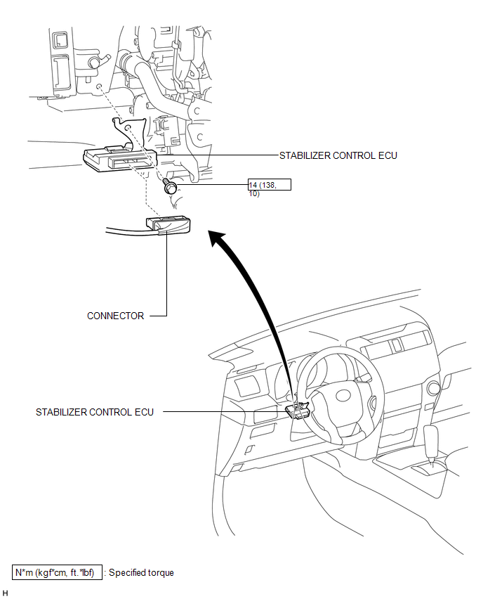
COMPONENTS
ILLUSTRATION
Removal
REMOVAL
PROCEDURE
1. DISCONNECT CABLE FROM NEGATIVE BATTERY TERMINAL
CAUTION:
Wait at least 90 seconds after disconnecting the cable from the negative (-) battery terminal to disable the SRS system.
NOTICE:
When disconnecting the cable, some systems need to be initialized after the cable
is reconnected (See page .gif) ).
).
2. REMOVE LOWER NO. 1 INSTRUMENT PANEL AIRBAG ASSEMBLY
(a) Remove the lower No. 1 instrument panel airbag assembly (See page
).
3. REMOVE STABILIZER CONTROL ECU
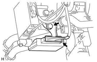
(a) Disconnect the connector.
(b) Remove the bolt and stabilizer control ECU.
NOTICE:
- Avoid any impact to the stabilizer control ECU.
- Replace the stabilizer control ECU with a new one if it is dropped.
Installation
INSTALLATION
PROCEDURE
1. INSTALL STABILIZER CONTROL ECU
(a) Install the stabilizer control ECU with the bolt.
Torque:
14 N·m {138 kgf·cm, 10 ft·lbf}
NOTICE:
- Replace the stabilizer control ECU with a new one if it is dropped.
- Make sure the bracket rotation stopper touches the installation position.
(b) Connect the connector.
NOTICE:
Securely connect the connector.
2. INSTALL LOWER NO. 1 INSTRUMENT PANEL AIRBAG ASSEMBLY
(a) Install the lower No. 1 instrument panel airbag assembly (See page
.gif) ).
).
3. CONNECT CABLE TO NEGATIVE BATTERY TERMINAL
NOTICE:
When disconnecting the cable, some systems need to be initialized after the cable
is reconnected (See page ).
 Zero Point Calibration of Acceleration Sensor Undone (C1879/79)
DESCRIPTION
The stabilizer control ECU receives the yaw rate and acceleration sensor zero
point information from the skid control ECU via CAN communication.
DTC Code
DTC Dete ...

Other materials about Toyota 4Runner:
Telephone Microphone Error (B1572)
DESCRIPTION
This DTC is stored when the DCM (Telematics Transceiver) detects a malfunction
in the telephone microphone assembly circuit.
DTC Code
DTC Detection Condition
Trouble Area
B1572
Curren ...
Fuel Receiver Gauge Malfunction
DESCRIPTION
The fuel sender gauge has a variable resistance mechanism. The resistance
decreases when the fuel amount increases, and the resistance increases when
the fuel amount decreases. The fuel receiver gauge changes based on the
resist ...

0.0062