Toyota 4Runner: Stereo Component Amplifier Power Source Circuit
DESCRIPTION
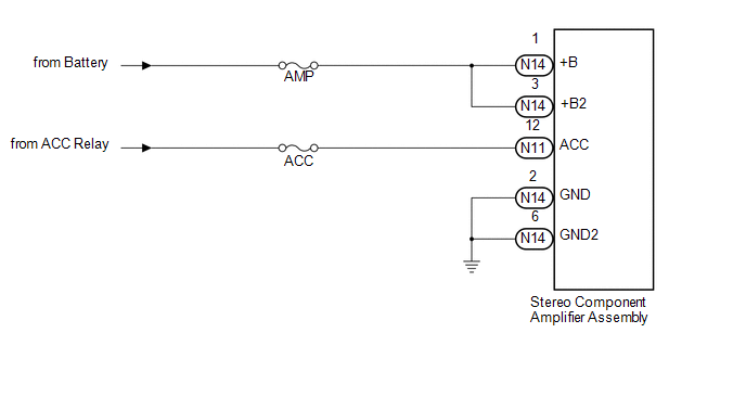
This circuit provides power to the stereo component amplifier assembly.
WIRING DIAGRAM
CAUTION / NOTICE / HINT
NOTICE:
Inspect the fuses for circuits related to this system before performing the following inspection procedure.
PROCEDURE
|
1. |
CHECK HARNESS AND CONNECTOR (STEREO COMPONENT AMPLIFIER ASSEMBLY - BATTERY AND BODY GROUND) |
|
(a) Disconnect the N11 and N14 stereo component amplifier assembly connectors. |
|
(b) Measure the resistance according to the value(s) in the table below.
Standard Resistance:
|
Tester Connection |
Condition |
Specified Condition |
|---|---|---|
|
N14-2 (GND) - Body ground |
Always |
Below 1 Ω |
|
N14-6 (GND2) - Body ground |
Always |
Below 1 Ω |
(c) Measure the voltage according to the value(s) in the table below.
Standard Voltage:
|
Tester Connection |
Condition |
Specified Condition |
|---|---|---|
|
N14-1 (+B) - N14-2 (GND) |
Always |
11 to 14 V |
|
N14-3 (+B2) - N14-2 (GND) |
Always |
11 to 14 V |
|
N11-12 (ACC) - N14-2 (GND) |
Ignition switch ACC |
11 to 14 V |
|
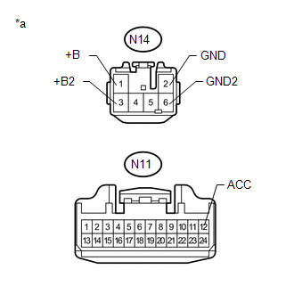
*a |
Front view of wire harness connector (to Stereo Component Amplifier Assembly) |
| OK | .gif) |
PROCEED TO NEXT SUSPECTED AREA SHOWN IN PROBLEM SYMPTOMS TABLE |
| NG | |
REPAIR OR REPLACE HARNESS AND CONNECTOR |
 Microphone Circuit between Microphone and Navigation Receiver Assembly
DESCRIPTION
The navigation receiver assembly and map light assembly (telephone microphone
assembly) are connected to each other using the microphone connection detection
signal lines. ...
 Navigation Receiver Assembly Power Source Circuit
DESCRIPTION
This is the power source circuit to operate the navigation receiver assembly.
WIRING DIAGRAM
CAUTION / NOTICE / HINT
NOTICE:
Inspect the fuses for circuits related to this system be ...
Other materials about Toyota 4Runner:
Cruise control
Use the cruise control to maintain a set speed without depressing the
accelerator pedal.
1. Indicators
2. Cruise control switch
Setting the vehicle speed
Press the “ON-OFF” button to activate the cruise control.
Cruise control indicator will co ...
Components
COMPONENTS
ILLUSTRATION
ILLUSTRATION
ILLUSTRATION
ILLUSTRATION
ILLUSTRATION
...

0.0136