Toyota 4Runner: System Diagram
Toyota 4Runner Service Manual / Vehicle Exterior / Exterior Panels / Trim / Automatic Running Board System / System Diagram
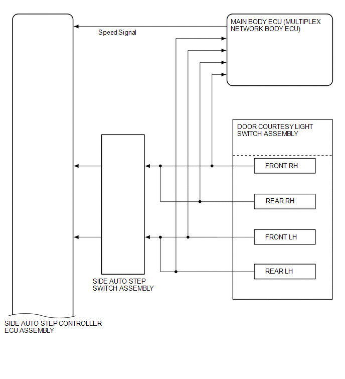
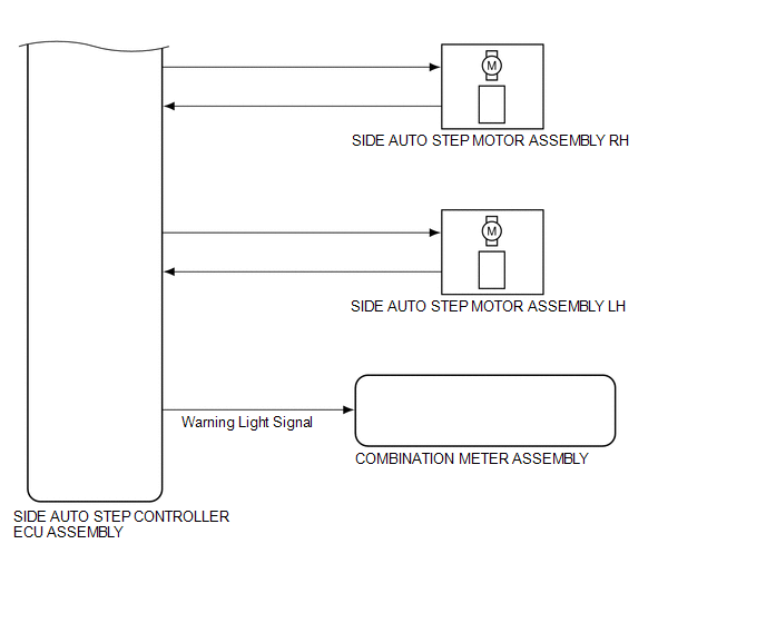
SYSTEM DIAGRAM
 Precaution
PRECAUTION
1. IGNITION SWITCH EXPRESSION
HINT:
The type of ignition switch used on this model differs according to the specifications
of the vehicle. The expressions listed in the table below are ...
 How To Proceed With Troubleshooting
CAUTION / NOTICE / HINT
HINT:
Use these procedures to troubleshoot the automatic running board system.
PROCEDURE
1.
VEHICLE BROUGHT TO WORKSHOP
...
Other materials about Toyota 4Runner:
Rear Power Window Switch
Components
COMPONENTS
ILLUSTRATION
Inspection
INSPECTION
PROCEDURE
1. INSPECT REAR POWER WINDOW REGULATOR SWITCH ASSEMBLY
(a) Measure the resistance according to the value(s) in the table below.
Standard Resistance:
...
How To Proceed With Troubleshooting
CAUTION / NOTICE / HINT
HINT:
Use these procedures to troubleshoot the engine immobiliser system.
*: Use the Techstream.
PROCEDURE
1.
VEHICLE BROUGHT TO WORKSHOP
NEXT
...
© 2016-2026 | www.to4runner.net

0.0256
0.0256