Toyota 4Runner: System Diagram
SYSTEM DIAGRAM
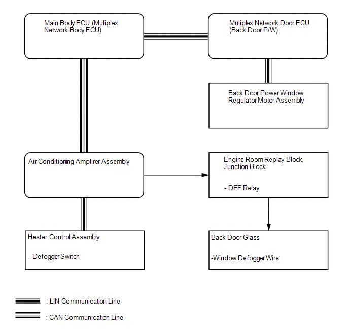 Communication Table
|
Transmitter |
Receiver |
Signal |
Line |
|---|---|---|---|
|
Heater control assembly |
Air conditioning amplifier assembly |
Defogger switch signal |
LIN |
|
Multiplex network door ECU (Back door P/W) |
Main body ECU (Multiplex network body ECU) |
Back door window position signal |
LIN |
|
Back door power window regulator motor |
Multiplex network door ECU (Back door P/W) |
Back door window position signal |
LIN |
|
Main body ECU (Multiplex network body ECU) |
Air conditioning amplifier assembly |
Back door window position signal |
CAN |
 System Description
SYSTEM DESCRIPTION
1. WINDOW DEFOGGER SYSTEM DESCRIPTION
The thin heater wires of the defogger system are attached to the rear window
and defog the rear window surface quickly. The system only ope ...
 How To Proceed With Troubleshooting
CAUTION / NOTICE / HINT
HINT:
Inspect the window defogger system after confirming that the back door
power window system of the power window control system is operating normally.
...
Other materials about Toyota 4Runner:
Luggage compartment features
Cargo hooks
Vehicles with third seats
Fold down the third seats.
Raise the hook to use.
The cargo hooks are provided for securing loose items.
Vehicles without third seats
Raise the hook to use.
The cargo hooks are provided for securing loose items ...
Disposal
DISPOSAL
PROCEDURE
1. DISPOSE OF STABILIZER CONTROL WITH ACCUMULATOR HOUSING ASSEMBLY
(a) Using a drill, make a hole in the areas of the accumulator housing
indicated in the illustration to discharge the gas inside.
CAUTION:
...

0.0085