Toyota 4Runner: System Diagram
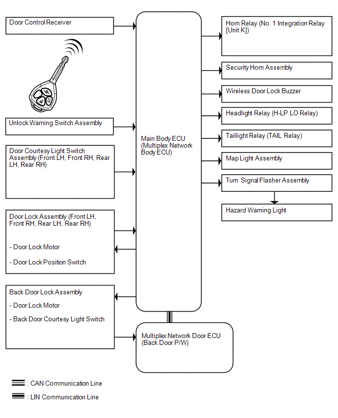
SYSTEM DIAGRAM
 Parts Location
PARTS LOCATION
ILLUSTRATION
ILLUSTRATION
ILLUSTRATION
ILLUSTRATION
...
 System Description
SYSTEM DESCRIPTION
1. WIRELESS DOOR LOCK CONTROL SYSTEM DESCRIPTION
(a) This system locks/unlocks the vehicle doors remotely. The wireless control
system has the following features:
The do ...
Other materials about Toyota 4Runner:
Operation Check
OPERATION CHECK
1. CHECK WINDOW LOCK SWITCH
HINT:
Before performing the window lock switch operation check, make sure that the
window lock switch is off (the switch is not pushed in).
(a) Check that the front passenger side power window, rear power windo ...
Door Courtesy Switch Circuit
DESCRIPTION
The main body ECU (multiplex network body ECU) receives a door open/closed signal
from each door courtesy light switch.
WIRING DIAGRAM
PROCEDURE
1.
READ VALUE USING TECHSTREAM (DOOR COURTESY LIGHT SWITCH)
(a ...
© 2016-2026 | www.to4runner.net

0.0079
0.0079