Toyota 4Runner: System Diagram
Toyota 4Runner Service Manual / Vehicle Interior / Seat / Climate Control Seat System / System Diagram
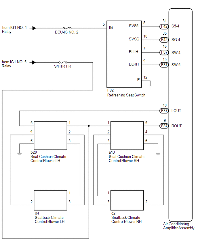
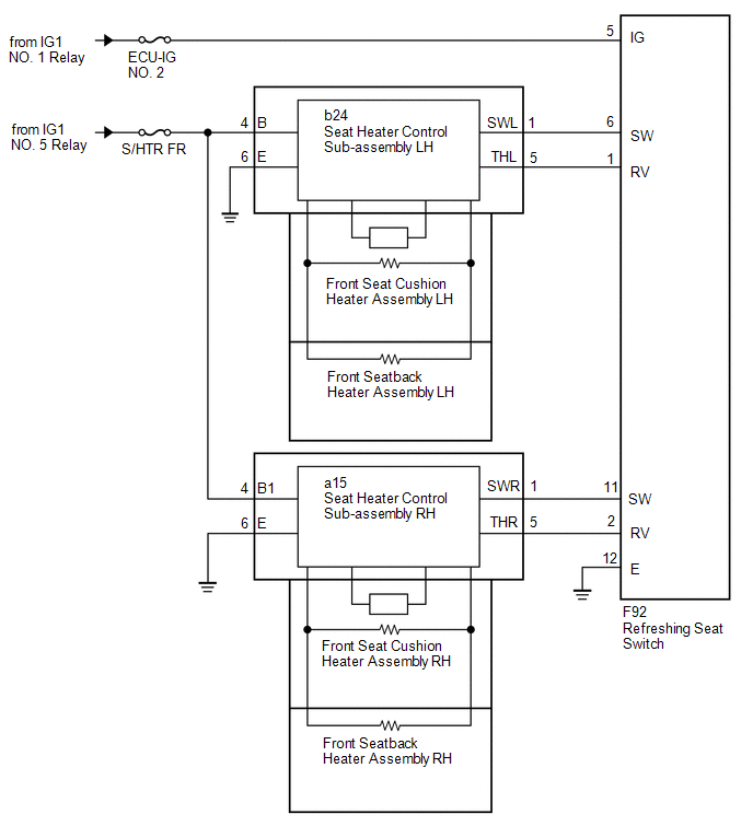
SYSTEM DIAGRAM
 System Description
SYSTEM DESCRIPTION
1. GENERAL
(a) The heater and blower both have 3 levels controlled by operating the dial-type
refreshing seat switch, which is located in the upper console panel.
(b) The on/of ...
 Operation Check
OPERATION CHECK
1. CHECK SEAT CUSHION CLIMATE CONTROL BLOWER
(a) Turn the engine switch on (IG).
(b) Set the refreshing seat switch blower side to level 3 (maximum).
(c) Check that the fan motor t ...
Other materials about Toyota 4Runner:
Front Airbag Sensor RH Malfunction (B1610/13)
DESCRIPTION
The front airbag sensor RH consists of the diagnostic circuit and frontal deceleration
sensor, etc.
If the center airbag sensor receives signals from the frontal deceleration sensor,
it determines whether the SRS should be activated.
DTC B16 ...
Lost Communication with Front Satellite Sensor Bus (B161A/8A)
DESCRIPTION
The front collision sensor circuit (front airbag sensor RH circuit and front
airbag sensor LH circuit) is composed of the center airbag sensor assembly, front
airbag sensor RH and front airbag sensor LH.
The front airbag sensor RH or front ai ...
© 2016-2026 | www.to4runner.net

0.0068
0.0068