Toyota 4Runner: System Diagram
SYSTEM DIAGRAM
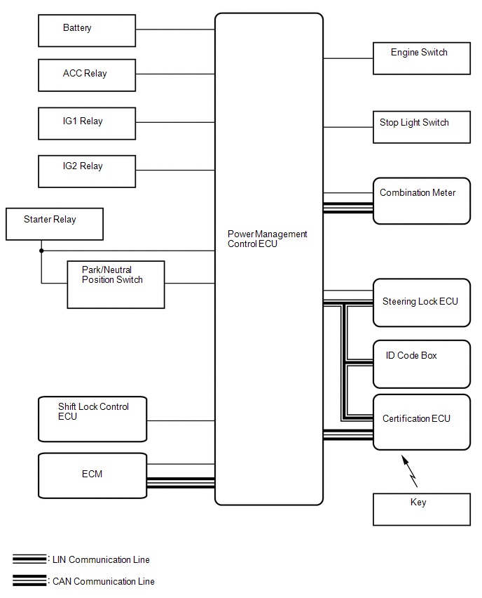 Communication Table
|
Transmitting ECU (Transmitter) |
Receiving ECU (Receiver) |
Signal |
Line |
|---|---|---|---|
|
ECM |
Power management control ECU |
Crankshaft position sensor signal |
CAN/Serial communication |
|
Combination meter |
Power management control ECU |
Vehicle speed signal |
CAN/Serial communication |
|
Steering lock ECU |
Power management control ECU |
Steering lock/unlock signal |
LIN/Serial communication |
|
Certification ECU |
Power management control ECU |
LIN master signal |
LIN |
|
Power management control ECU |
Certification ECU |
ID required signal |
LIN |
|
Key existence condition signal |
CAN |
 System Description
SYSTEM DESCRIPTION
1. PUSH-BUTTON START DESCRIPTION
(a) The push-button start function uses a push-type engine switch, which the
driver can operate by merely carrying the key. This system consists ...
 How To Proceed With Troubleshooting
CAUTION / NOTICE / HINT
HINT:
Use these procedures to troubleshoot the push-button start function.
*: Use the Techstream.
PROCEDURE
1.
VEHICLE BROUGHT T ...
Other materials about Toyota 4Runner:
Fail-safe Chart
FAIL-SAFE CHART
1. FAIL-SAFE
This function minimizes the loss of ECT functions when a malfunction occurs in
a sensor or solenoid.
Malfunction Part
Function
No. 1 ATF temperature sensor
During a No. 1 ATF t ...
Installation
INSTALLATION
CAUTION / NOTICE / HINT
CAUTION:
Wear protective gloves. Sharp areas on the parts may injure your hands.
HINT:
Use the same procedure for the RH and LH sides.
The procedure listed below is for the LH side.
PROCEDURE
1. INS ...

0.0068