Toyota 4Runner: System Diagram
SYSTEM DIAGRAM
 Communication Table
|
Sender |
Receiver |
Signal |
Line |
|---|---|---|---|
|
ECM |
Skid control ECU |
|
CAN communication |
|
Skid control ECU |
ECM |
|
CAN communication |
|
Skid control ECU |
Combination Meter Assembly |
|
CAN communication |
|
Four wheel drive control ECU |
Skid control ECU |
|
CAN communication |
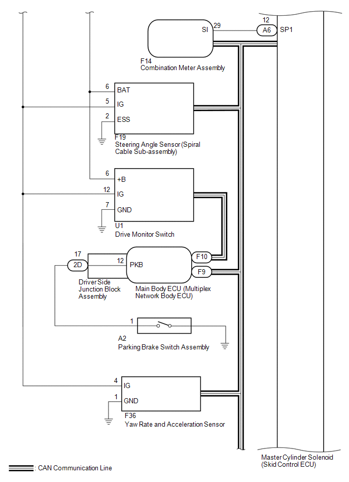
|
Steering Angle Sensor (Spiral Cable Sub-assembly) |
Skid control ECU |
Steering angle signal |
CAN communication |
 Parts Location
PARTS LOCATION
ILLUSTRATION
ILLUSTRATION
...
 System Description
SYSTEM DESCRIPTION
1. SYSTEM DESCRIPTION
HINT:
The skid control ECU is built into the hydraulic brake booster.
(a) ABS (Anti-lock Brake System)
The ABS helps prevent the wheels from locking when ...
Other materials about Toyota 4Runner:
Installation
INSTALLATION
CAUTION / NOTICE / HINT
CAUTION:
Wear protective gloves. Sharp areas on the parts may injure your hands.
HINT:
A bolt without a torque specification is shown in the standard bolt chart (See
page ).
PROCEDURE
1. INSTALL NO. 1 SEAT 3 POINT ...
Front Vertical Sensor Malfunction (B2652)
DESCRIPTION
When the front power seat switch LH does not receive a sensor signal despite
upward or downward movement of the front of the seat cushion by power seat motor
operation, this DTC is stored.
DTC Code
DTC Detection Conditio ...

0.0113