Toyota 4Runner: Taillight Relay Circuit
DESCRIPTION
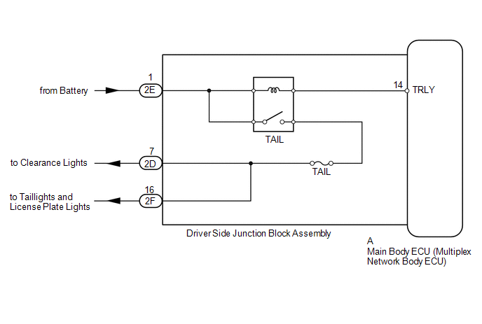
The main body ECU receives headlight dimmer switch information signals, and illuminates the clearance lights, taillights and license plate lights.
WIRING DIAGRAM
CAUTION / NOTICE / HINT
NOTICE:
Inspect the fuses and bulbs for circuits related to this system before performing the following inspection procedure.
PROCEDURE
|
1. |
PERFORM ACTIVE TEST USING TECHSTREAM (TAILLIGHT RELAY) |
(a) Using the Techstream, perform the Active Test (See page
.gif) ).
).
Main Body
|
Tester Display |
Test Part |
Control Range |
Diagnostic Note |
|---|---|---|---|
|
Taillight Relay |
Taillight relay |
ON/OFF |
- |
OK:
Taillight relay operates (taillights illuminate).
| OK | .gif) |
PROCEED TO NEXT SUSPECTED AREA SHOWN IN PROBLEM SYMPTOMS TABLE |
|
.gif)
|
2. |
CHECK HARNESS AND CONNECTOR (BATTERY - MAIN BODY ECU) |
|
(a) Remove the main body ECU (See page
|
|
(b) Measure the voltage according to the value(s) in the table below.
Standard Voltage:
|
Tester Connection |
Condition |
Specified Condition |
|---|---|---|
|
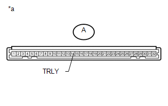
A-14 (TRLY) - Body ground |
Always |
11 to 14 V |
|
*a |
Front view of wire harness connector (to Main Body ECU) |
| OK | |
PROCEED TO NEXT SUSPECTED AREA SHOWN IN PROBLEM SYMPTOMS TABLE |
| NG | |
REPAIR OR REPLACE HARNESS OR CONNECTOR |
 Front Fog Light Circuit
DESCRIPTION
The main body ECU receives headlight dimmer switch information signals, and illuminates
the front fog light.
WIRING DIAGRAM
CAUTION / NOTICE / HINT
NOTICE:
Inspect the fuses and b ...
 Rear Combination Light Assembly
Components
COMPONENTS
ILLUSTRATION
Removal
REMOVAL
CAUTION / NOTICE / HINT
HINT:
Use the same procedure for both the RH and LH sides.
The procedure listed below is for the LH ...
Other materials about Toyota 4Runner:
Removal
REMOVAL
PROCEDURE
1. DISCONNECT CABLE FROM NEGATIVE BATTERY TERMINAL
NOTICE:
When disconnecting the cable, some systems need to be initialized after the cable
is reconnected (See page ).
2. REMOVE LOWER STEERING COLUMN COVER
(a) Turn the st ...
Torque Converter Clutch And Drive Plate
Inspection
INSPECTION
PROCEDURE
1. INSPECT TORQUE CONVERTER CLUTCH ASSEMBLY
(a) Inspect the 1-way clutch.
(1) Install SST to the inner race of the 1-way clutch.
SST: 09350-32014
09351-32020
(2) Press on the serrations of the starter with a finger a ...

0.0076