Toyota 4Runner: TC and CG Terminal Circuit
DESCRIPTION
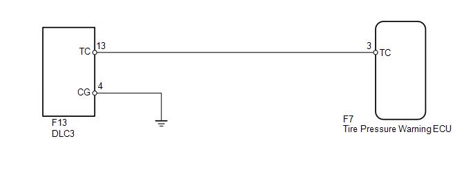
DTC output mode is set by connecting terminals 13 (TC) and 4 (CG) of the DLC3. The DTCs are output by the blinking of the tire pressure warning light.
WIRING DIAGRAM
HINT:
When each warning light blinks continuously, a ground short in the wiring of terminal TC of the DLC3 or an internal ground short in each ECU is suspected.
CAUTION / NOTICE / HINT
NOTICE:
- When replacing the tire pressure warning ECU, read the transmitter IDs stored in the old ECU using the Techstream and write them down before removal.
- It is necessary to perform registration of the transmitter IDs into
the tire pressure warning ECU after the ECU and/or the tire pressure warning
valve and transmitter has been replaced (See page
.gif) ).
).
PROCEDURE
|
1. |
CHECK HARNESS AND CONNECTOR (DLC3 - ECU AND BODY GROUND) |
(a) Disconnect the F7 ECU connector.
(b) Measure the resistance according to the value(s) in the table below.
Standard Resistance:
|
Tester Connection |
Condition |
Specified Condition |
|---|---|---|
|
F7-3 (TC) - F13-13 (TC) |
Always |
Below 1 Ω |
|
F7-3 (TC) - Body ground |
Always |
10 kΩ or higher |
|
F13-4 (CG) - Body ground |
Always |
Below 1 Ω |
| OK | .gif) |
CHECK ECU POWER SOURCE CIRCUIT |
| NG | |
REPAIR OR REPLACE HARNESS OR CONNECTOR OR EACH ECU |
 ECU Power Source Circuit
DESCRIPTION
This is the power source for the tire pressure warning ECU.
WIRING DIAGRAM
CAUTION / NOTICE / HINT
NOTICE:
When replacing the tire pressure warning ECU, read the IDs stored ...

Other materials about Toyota 4Runner:
Vehicle Speed Signal Error (Test Mode DTC) (C2191/91)
DESCRIPTION
The tire pressure warning ECU receives a vehicle speed signal from the combination
meter. This DTC is stored upon entering test mode and cleared when a vehicle speed
signal of 20 km/h (12 mph) is detected for 3 seconds or more. This DTC is sto ...
Audio Receiver Assembly Communication Stop Mode
DESCRIPTION
Detection Item
Symptom
Trouble Area
Audio Receiver Assembly Communication Stop Mode
Either condition is met:
"Display and Navigation (AVN1)" is not displayed on t ...

0.0261