Toyota 4Runner: Telephone Microphone Error (B1572)
DESCRIPTION
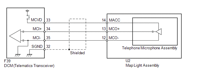
This DTC is stored when the DCM (Telematics Transceiver) detects a malfunction in the telephone microphone assembly circuit.
|
DTC Code |
DTC Detection Condition |
Trouble Area |
|---|---|---|
|
B1572 |
Current of MCVD reaches the malfunction criteria for 10 seconds when the ignition switch is ON. |
|
WIRING DIAGRAM
PROCEDURE
|
1. |
CHECK FOR DTC |
(a) Turn the ignition switch off.
(b) Connect the Techstream to the DLC3.
(c) Turn the ignition switch to ON and wait for 10 seconds.
(d) Perform "Health Check" and check for current DTCs (See page
.gif) ).
).
Result
|
Result |
Proceed to |
|---|---|
|
DTC B1572 is output |
A |
|
DTC B1572 is not output |
B |
| B | .gif) |
CHECK FOR INTERMITTENT PROBLEMS |
|
.gif)
|
2. |
CHECK MAP LIGHT ASSEMBLY (TELEPHONE MICROPHONE POWER SOURCE) |
|
(a) Remove the map light assembly with the connector connected (See page
|
|
(b) Measure the voltage according to the value(s) in the table below
Standard Voltage:
|
Tester Connection |
Switch Condition |
Specified Condition |
|---|---|---|
|
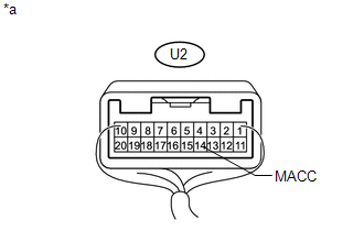
U2-14 (MACC) - Body ground |
Ignition switch ON |
4 to 6 V |
|
*a |
Component with harness connected (Map Light Assembly) |
| NG | |
GO TO STEP 5 |
|
|
3. |
CHECK HARNESS AND CONNECTOR (DCM - MAP LIGHT ASSEMBLY) |
|
(a) Disconnect the F39 DCM (Telematics Transceiver) connector. |
|
(b) Disconnect the U2 map light assembly connector.
(c) Measure the resistance according to the value(s) in the table below.
Standard Resistance:
|
Tester Connection |
Condition |
Specified Condition |
|---|---|---|
|
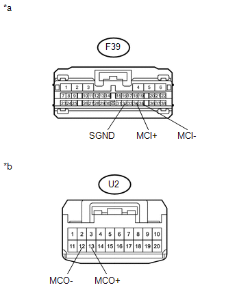
F39-34 (MCI+) - U2-13 (MCO+) |
Always |
Below 1 Ω |
|
F39-35 (MCI-) - U2-12 (MCO-) |
Always |
Below 1 Ω |
|
F39-34 (MCI+) - Body ground |
Always |
10 kΩ or higher |
|
F39-35 (MCI-) - Body ground |
Always |
10 kΩ or higher |
|
F39-32 (SGND) - Body ground |
Always |
10 kΩ or higher |
|
*a |
Front view of wire harness connector (to DCM [Telematics Transceiver]) |
|
*b |
Front view of wire harness connector (to Map Light Assembly) |
| NG | |
REPAIR OR REPLACE HARNESS OR CONNECTOR |
|
|
4. |
REPLACE TELEPHONE MICROPHONE ASSEMBLY |
(a) Replace the telephone microphone assembly with a normal one and check that
the same problem does not occur again (See page
).
OK:
The system returns to normal.
| OK | |
END |
| NG | |
REPLACE MAP LIGHT ASSEMBLY |
|
5. |
CHECK DCM (TELEMATICS TRANSCEIVER) (TELEPHONE MICROPHONE POWER SOURCE) |
|
(a) Remove the DCM (Telematics Transceiver) with the connectors connected
(See page |
|
(b) Measure the voltage according to the value(s) in the table below.
Standard Voltage:
|
Tester Connection |
Switch Condition |
Specified Condition |
|---|---|---|
|
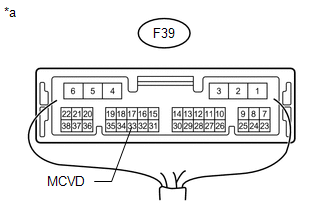
F39-33 (MCVD) - Body ground |
Ignition switch ON |
4 to 6 V |
|
*a |
Component with harness connected (DCM [Telematics Transceiver]) |
| OK | |
REPAIR OR REPLACE HARNESS OR CONNECTOR |
|
|
6. |
REPLACE DCM (TELEMATICS TRANSCEIVER) |
(a) Replace the DCM (Telematics Transceiver) (See page
).
NOTICE:
- The ignition switch must be off.
- Do not replace the DCM (Telematics Transceiver) with one from another vehicle.
| NEXT | |
PERFORM DCM ACTIVATION |
 Manual (SOS) Switch Green Indicator Malfunction (B1571)
DESCRIPTION
This DTC is stored when the DCM (Telematics Transceiver) detects an open or short
in the manual (SOS) switch green indicator circuit of the manual (SOS) switch. The
manual (SOS) switc ...
 Short in Telephone Antenna Circuit (B1573,B15CB)
DESCRIPTION
This DTC is stored when the DCM (Telematics Transceiver) detects an open or a
short in the telephone and GPS antenna circuit. The DCM (Telematics Transceiver)
sends and receives signa ...
Other materials about Toyota 4Runner:
Rear Coil Spring
Components
COMPONENTS
ILLUSTRATION
Removal
REMOVAL
CAUTION / NOTICE / HINT
HINT:
Use the same procedure for the RH and LH sides.
The procedure listed below is for the LH side.
PROCEDURE
1. REMOVE REAR WHEEL
2. REMOVE REAR STAB ...
Installation
INSTALLATION
PROCEDURE
1. INSTALL INDOOR NO. 2 ELECTRICAL KEY ANTENNA ASSEMBLY
(a) Attach the 2 claws to install the indoor No. 2 electrical key antenna.
(b) Connect the connector.
2. INSTALL NO. 1 LUGG ...

0.0179