Toyota 4Runner: Terminals Of Ecu
TERMINALS OF ECU
 Text in Illustration
|
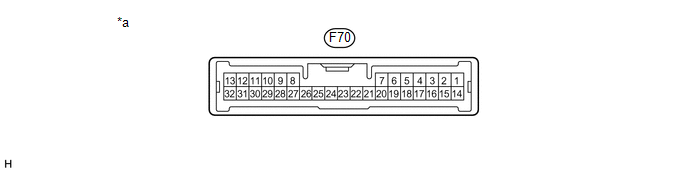
*a |
Component with harness connected (Stabilizer Control ECU) |
- |
- |
|
Terminal No. (Symbol) |
Wiring Color |
Terminal Description |
Condition |
Specified Condition |
|---|---|---|---|---|
|
F70-1 (SLAL) - Body ground |
LG - Body ground |
Stabilizer control solenoid valve output signal (for Upper Chamber) |
Ignition switch ON Vehicle stopped |
Below 1 V |
|
F70-3 (SLAU) - Body ground |
P - Body ground |
Stabilizer control solenoid valve output signal (for Lower Chamber) |
Ignition switch ON Vehicle stopped |
Below 1 V |
|
F70-6 (SGP1) - Body ground |
G - Body ground |
Pressure sensor ground |
Always |
Below 1 V |
|
F70-15 (SBP1) - Body ground |
R - Body ground |
Power source (Pressure sensor) |
Ignition switch ON |
4.75 to 5.25 V |
|
F70-17 (SOP1) - Body ground |
GR - Body ground |
Pressure sensor input signal |
Ignition switch ON |
0.4 to 4.6 V |
|
F70-22 (GND) - Body ground |
W-B - Body ground |
Ground |
Always |
Below 1 Ω |
|
F70-24 (IG) - Body ground |
B - Body ground |
Power source |
Ignition switch ON |
11 to 14 V |
|
F70-28 (CANL) - F70-29 (CANH) |
W - P |
CAN communication line |
Ignition switch off |
54 to 69 Ω |
 Problem Symptoms Table
PROBLEM SYMPTOMS TABLE
HINT:
Use the table below to help determine the cause of problem symptoms.
If multiple suspected areas are listed, the potential causes of the symptoms
are lis ...
 Diagnosis System
DIAGNOSIS SYSTEM
1. DIAGNOSIS SYSTEM
(a) Indicator light
(1) During vehicle stabilizer control operation, the KDSS indicator light comes
on when there is a malfunction in the KDSS.
NOTICE:
...
Other materials about Toyota 4Runner:
Installation
INSTALLATION
PROCEDURE
1. INSTALL REAR DIFFERENTIAL CARRIER ASSEMBLY
(a) Remove any dust and oil from the differential carrier assembly and the contact
surfaces of the axle housing.
(b) Install a new gasket and the differential carrier assembly with the ...
Installation
INSTALLATION
CAUTION / NOTICE / HINT
HINT:
A bolt without a torque specification is shown in the standard bolt chart (See
page ).
PROCEDURE
1. INSTALL PINTLE HOOK SUPPORT TUBE SUB-ASSEMBLY (w/ Pintle Hook)
(a) Install the pintle hook support tube sub- ...

0.0074