Toyota 4Runner: Terminals Of Ecu
TERMINALS OF ECU
1. CHECK TIRE PRESSURE WARNING ECU
HINT:
Inspect the connector from the back side.

(a) Disconnect the F7 ECU connector.
(b) Measure the voltage according to the value(s) in the table below.
|
Terminal No. (Symbol) |
Wiring Color |
Terminal Description |
Condition |
Specified Condition |
|---|---|---|---|---|
|
F7-7 (IG) - F7-9 (GND) |
G - W-B |
IG power source |
Ignition switch ON |
11 to 14 V |
(c) Connect the F7 ECU connector.
(d) Measure the voltage and resistance according to the value(s) in the table below.
|
Terminal No. (Symbol) |
Wiring Color |
Terminal Description |
Condition |
Specified Condition |
|---|---|---|---|---|
|
F7-2 (SPD) - F7-9 (GND) |
SB - W-B |
Vehicle speed signal |
Vehicle being driven |
Pulse generation (see waveform 1) |
|
F7-3 (TC) - F7-9 (GND) |
R - W-B |
TC terminal |
Terminal TC not connected |
11 to 14 V |
|
F7-4 (TACH) - F7-9 (GND) |
P - W-B |
Engine speed signal |
Engine running |
Pulse generation (see waveform 2) |
|
F7-5 (IND) - F7-9 (GND) |
G - W-B |
Tire pressure warning light output signal |
After ignition switch turned to ON, tire pressure warning light illuminates for 3 seconds |
0.9 to 3.2 V |
|
Ignition switch ON Tire pressure warning light off |
3.2 V or higher |
|||
|
F7-6 (RF5V) - F7-9 (GND) |
LG - W-B |
Tire pressure warning antenna and receiver power source |
Ignition switch ON |
4.5 to 5.5 V |
|
F7-9 (GND) - Body ground |
W-B - Body ground |
Ground |
Always |
Below 1 Ω |
|
F7-10 (SIL) - F7-9 (GND) |
G - W-B |
Diagnosis tester communication line |
Ignition switch ON Communication not performed with tester |
11 to 14 V |
|
F7-11 (GND2) - F7-9 (GND) |
GR - W-B |
Tire pressure warning antenna and receiver ground |
Always |
Below 1 Ω |
|
F7-12 (RDA) - F7-9 (GND) |
SB - W-B |
Tire pressure warning antenna and receiver signal |
Ignition switch ON |
11 to 14 V |
(e) Using an oscilloscope, check waveform 1.
|
Item |
Contents |
|---|---|
|
Terminal No. (Symbol) |
F7-2 (SPD) - F7-9 (GND) |
|
Tool Setting |
5 V/DIV., 200 ms/DIV. |
|
Vehicle Condition |
Vehicle being driven at approximately 20 km/h (12 mph) |
HINT:
The wavelength becomes shorter as the vehicle speed increases.
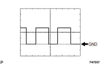
(f) Using an oscilloscope, check waveform 2.
|
Item |
Contents |
|---|---|
|
Terminal No. (Symbol) |
F7-4 (TACH) - F7-9 (GND) |
|
Tool Setting |
5 V/DIV., 10 ms/DIV. |
|
Vehicle Condition |
Idling |
HINT:
The wavelength becomes shorter as the engine speed increases.
 Problem Symptoms Table
PROBLEM SYMPTOMS TABLE
HINT:
Use the table below to help determine the cause of problem symptoms.
If multiple suspected areas are listed, the potential causes of the symptoms
are lis ...
 Diagnosis System
DIAGNOSIS SYSTEM
1. CHECK WARNING LIGHT
NOTICE:
When there is a problem with the tire pressure warning system, the tire
pressure warning light blinks at 0.5 second intervals and comes o ...
Other materials about Toyota 4Runner:
Dtc Check / Clear
DTC CHECK / CLEAR
1. CHECK DTC (CHECK USING TECHSTREAM)
(a) Connect the Techstream to the DLC3.
(b) Turn the ignition switch to ON.
(c) Turn the Techstream on.
(d) Enter the following menus: Body Electrical / Navigation System / Trouble
Codes.
(e) Chec ...
Engine Speed Signal Error (Test Mode DTC) (C2194/94)
DESCRIPTION
The tire pressure warning ECU receives an engine speed signal from the ECM. This
DTC is stored upon entering test mode and cleared when an engine speed signal of
1000 rpm is detected for 3 seconds or more. This DTC is stored only in test mode. ...

0.0075