Toyota 4Runner: Terminals Of Ecu
TERMINALS OF ECU
1. CHECK DRIVER SIDE JUNCTION BLOCK ASSEMBLY, MAIN BODY ECU (MULTIPLEX NETWORK BODY ECU)
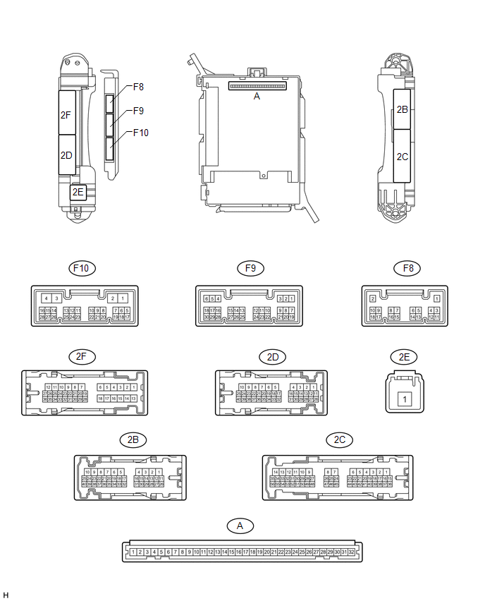
(a) Remove the main body ECU (See page .gif) ).
).
(b) Measure the resistance and voltage according to the value(s) in the table below.
|
Terminal No. (Symbol) |
Wiring Color |
Terminal Description |
Condition |
Specified Condition |
|---|---|---|---|---|
|
A-29 (ACC) - Body ground |
- |
ACC power supply |
Ignition switch ACC |
11 to 14 V |
|
A-30 (BECU) - Body ground |
- |
Battery power supply |
Always |
11 to 14 V |
|
A-32 (IG) - Body ground |
- |
Ignition power supply |
Ignition switch ON |
11 to 14 V |
|
A-11 (GND1) - Body ground |
- |
Ground |
Always |
Below 1 Ω |
|
F10-3 (GND2) - Body ground |
W-B - Body ground |
Ground |
Always |
Below 1 Ω |
If the result is not as specified, there may be a malfunction on the wire harness side.
(c) Install the main body ECU (See page ).
(d) Measure the voltage according to the value(s) in the table below.
|
Terminal No. (Symbol) |
Wiring Color |
Terminal Description |
Condition |
Specified Condition |
|---|---|---|---|---|
|
F9-3 (HAZ) - 2B-4 (GND1) |
W - W-B |
Hazard warning signal light signal input |
Hazard warning signal switch on |
Below 1 V |
|
Hazard warning signal switch off |
11 to 14 V |
|||
|
F9-5 (HU) - 2B-4 (GND1) |
LG - W-B |
Headlight dimmer switch high signal input |
Headlight dimmer switch in high |
Below 1 V |
|
Headlight dimmer switch in low |
11 to 14 V |
|||
|
F9-8 (HF) - 2B-4 (GND1) |
V - W-B |
Headlight dimmer switch high flash signal input |
Headlight dimmer switch in high flash position |
Below 1 V |
|
Headlight dimmer switch not in high flash position |
11 to 14 V |
|||
|
F9-20 (CLTB) - 2B-4 (GND1)* |
P - W-B |
Automatic light control sensor power supply output |
Ignition switch off |
Below 1 V |
|
Ignition switch ON and headlight dimmer switch in AUTO position |
11 to 14 V |
|||
|
F9-21 (CLTS) - 2B-4 (GND1)* |
R - W-B |
Automatic light control sensor signal input |
Ignition switch off |
Below 1 V |
|
Automatic light control system operates |
Pulse generation (See waveform 1) |
|||
|
F9-27 (FFOG) - 2B-4 (GND1) |
L - W-B |
Front fog light switch input |
Front fog light switch on |
Below 1 V |
|
Front fog light switch off |
11 to 14 V |
|||
|
F9-28 (A) - 2B-4 (GND1)* |
W - W-B |
Headlight dimmer switch AUTO signal input |
Headlight dimmer switch in AUTO |
Below 1 V |
|
Headlight dimmer switch not in AUTO |
11 to 14 V |
|||
|
F9-29 (HEAD) - 2B-4 (GND1) |
SB - W-B |
Headlight dimmer switch head signal input |
Headlight dimmer switch in head |
Below 1 V |
|
Headlight dimmer switch not in head |
11 to 14 V |
|||
|
F9-30 (TAIL) - 2B-4 (GND1) |
R - W-B |
Headlight dimmer switch tail signal input |
Headlight dimmer switch in tail or head |
Below 1 V |
|
Headlight dimmer switch in neither tail nor head |
11 to 14 V |
|||
|
2D-7 (TRLY) - 2B-4 (GND1) |
G - W-B |
Clearance light signal output |
Headlight dimmer switch in tail position |
11 to 14 V |
|
Headlight dimmer switch not in tail position |
Below 1 V |
|||
|
2D-9 (FFGO) - 2B-4 (GND1) |
W - W-B |
Front fog light signal output |
Headlight dimmer switch in tail and front fog light switch on |
Below 1 V |
|
Front fog light switch off |
11 to 14 V |
|||
|
2D-24 (DIM) - 2B-4 (GND1) |
P - W-B |
H-LP HI relay drive output |
Headlight dimmer switch in high or high flash |
Below 1 V |
|
Headlight dimmer switch not in high or high flash |
11 to 14 V |
|||
|
2D-40 (HRLY) - 2B-4 (GND1) |
P - W-B |
H-LP LO relay drive output |
Headlight dimmer switch in head |
Below 1 V |
|
Headlight dimmer switch not in head |
11 to 14 V |
|||
|
2E-1 (TRLY) - 2B-4 (GND1) |
W - W-B |
Battery power supply |
Always |
11 to 14 V |
|
2F-16 (TRLY) - 2B-4 (GND1) |
G - W-B |
Taillight and license plate light signal output |
Headlight dimmer switch in tail position |
11 to 14 V |
|
Headlight dimmer switch not in tail position |
Below 1 V |
|||
|
2F-27 (FLCY) - 2B-4 (GND1) |
R - W-B |
Front door courtesy light switch LH input |
Front door LH open |
Below 1 V |
|
Front door LH closed |
11 to 14 V |
- *: w/ Automatic Light Control System
If the result is not as specified, the main body ECU may have a malfunction.
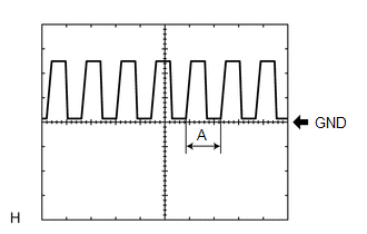
(1) Waveform 1
|
Item |
Content |
|---|---|
|
Terminal No. (Symbol) |
F9-21 (CLTS) - 2B-4 (GND1) |
|
Tool setting |
5 V/DIV., 5 ms./DIV. |
|
Condition |
Ignition switch ON Headlight dimmer switch AUTO Automatic light control sensor with a hand → Automatic light control sensor covered exposed to ambient light |
HINT:
If the ambient light becomes brighter, width A becomes narrower.
 Problem Symptoms Table
PROBLEM SYMPTOMS TABLE
HINT:
Use the table below to help determine the cause of problem symptoms. If multiple
suspected areas are listed, the potential causes of the symptoms are listed in order
...
 Diagnosis System
DIAGNOSIS SYSTEM
1. DESCRIPTION
(a) Lighting system data and the Diagnostic Trouble Codes (DTCs) can be read
from the Data Link Connector 3 (DLC3) of the vehicle. When the system seems to be
mal ...
Other materials about Toyota 4Runner:
Disassembly
DISASSEMBLY
PROCEDURE
1. REMOVE NO. 1 POWER OUTLET SOCKET ASSEMBLY
2. REMOVE NO. 1 POWER OUTLET SOCKET COVER
3. REMOVE REAR CONSOLE END PANEL
(a) Detach the 4 clips and 4 claws to remove the rear console end panel.
...
System Description
SYSTEM DESCRIPTION
1. SEAT BELT WARNING SYSTEM DESCRIPTION
If a seat belt is not fastened, this system flashes the seat belt warning light
or sounds the seat belt warning buzzer as a reminder.
(a) Driver side seat belt warning light:
The seat belt warnin ...

0.0268