Toyota 4Runner: Terminals Of Ecu
TERMINALS OF ECU
1. CHECK DRIVER SIDE JUNCTION BLOCK ASSEMBLY AND MAIN BODY ECU (MULTIPLEX NETWORK BODY ECU)
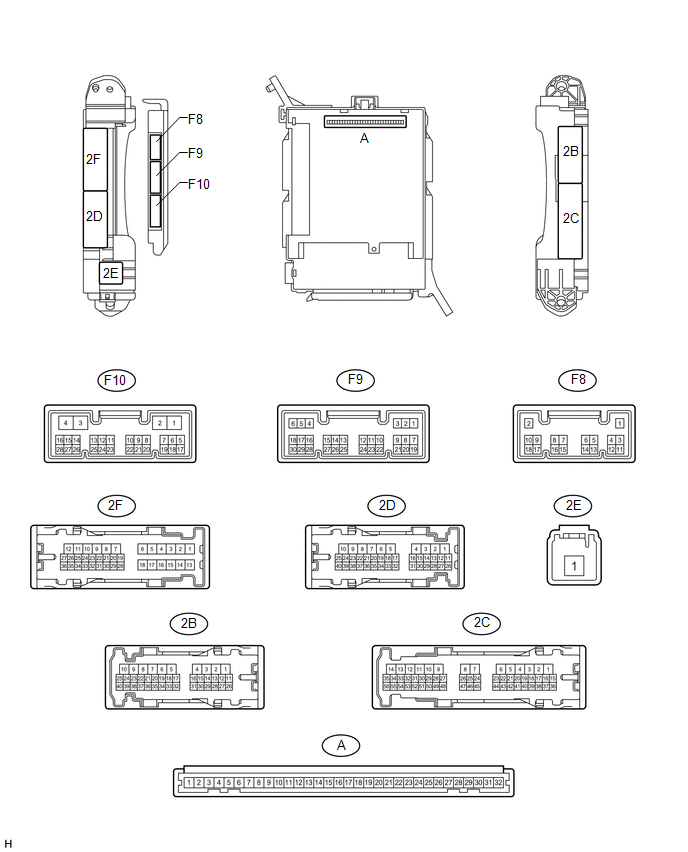
(a) Remove the main body ECU (multiplex network body ECU) (See page
.gif) ).
).
(b) Measure the voltage and resistance according to the value(s) in the table below.
|
Terminal No. (Symbol) |
Wiring Color |
Terminal Description |
Condition |
Specified Condition |
|---|---|---|---|---|
|
A-30 (BECU) - Body ground |
- |
Battery power supply |
Always |
11 to 14 V |
|
A-31 (ALTB) - Body ground |
- |
Battery power supply |
Always |
11 to 14 V |
|
A-32 (IG) - Body ground |
- |
Ignition switch power supply |
Ignition switch ON |
11 to 14 V |
|
A-32 (IG) - Body ground |
- |
Ignition switch power supply |
Ignition switch off |
Below 1 V |
|
A-29 (ACC) - Body ground |
- |
ACC power supply |
Ignition switch ACC |
11 to 14 V |
|
A-29 (ACC) - Body ground |
- |
ACC power supply |
Ignition switch off |
Below 1 V |
|
A-11 (GND1) - Body ground |
- |
Ground |
Always |
Below 1 Ω |
|
F10-3 (GND2) - Body ground |
W-B - Body ground |
Ground |
Always |
Below 1 Ω |
|
F9-17 (KSW) - Body ground |
B - Body ground |
Unlock warning switch input |
No key in ignition key cylinder |
10 kΩ or higher |
|
F9-17 (KSW) - Body ground |
B - Body ground |
Unlock warning switch input |
Key inserted in ignition key cylinder |
Below 1 Ω |
If the result is not as specified, there may be a malfunction in the wire harness.
(c) Install the main body ECU (multiplex network body ECU).
(d) Measure the voltage according to the value(s) in the table below.
|
Terminal No. (Symbol) |
Wiring Color |
Terminal Description |
Condition |
Specified Condition |
|---|---|---|---|---|
|
2F-27 (FLCY) - Body ground |
R - Body ground |
Front door LH courtesy switch input |
Front door LH open |
Below 1 V |
|
2F-27 (FLCY) - Body ground |
R - Body ground |
Front door LH courtesy switch input |
Front door LH closed |
11 to 14 V |
If the result is not as specified, the main body ECU (multiplex network body ECU) or driver side junction block assembly may have a malfunction.
 Problem Symptoms Table
PROBLEM SYMPTOMS TABLE
HINT:
Use the table below to help determine the cause of problem symptoms.
If multiple suspected areas are listed, the potential causes of the symptoms
are lis ...
 Data List / Active Test
DATA LIST / ACTIVE TEST
1. READ DATA LIST
HINT:
Using the Techstream to read the Data List allows the values or states of switches,
sensors, actuators and other items to be read without removing ...
Other materials about Toyota 4Runner:
USB Audio System Recognition/Play Error
DESCRIPTION
When a USB device or "iPod" is connected to the USB jack of the No. 1 stereo
jack adapter assembly, it must have playable files. The device must also communicate
with and be recognized by the navigation receiver assembly. This diagno ...
Removal
REMOVAL
CAUTION / NOTICE / HINT
PROCEDURE
1. REMOVE STEERING WHEEL ASSEMBLY
(a) Remove the steering wheel assembly (See page
).
2. REMOVE LOWER STEERING COLUMN COVER
3. REMOVE UPPER STEERING COLUMN COVER
4. REMOVE SPIRAL CABLE SUB-ASSEMBLY
...

0.0266