Toyota 4Runner: Traction Off Switch
Components
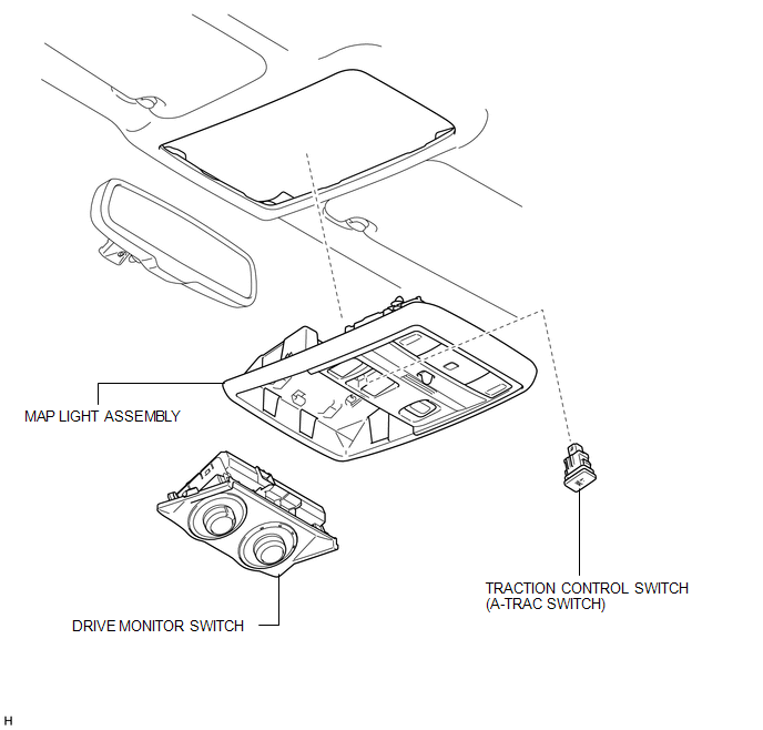
COMPONENTS
ILLUSTRATION
Removal
REMOVAL
PROCEDURE
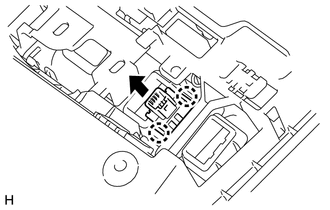
1. REMOVE DRIVE MONITOR SWITCH
.gif)
2. REMOVE MAP LIGHT ASSEMBLY
|
(a) Remove the screws. |
|
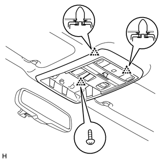
(b) Detach the 2 clips and remove the map light assembly.
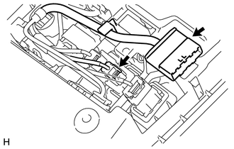
3. REMOVE TRACTION CONTROL SWITCH (A-TRAC SWITCH)
|
(a) Disconnect the 2 connectors. |
|
|
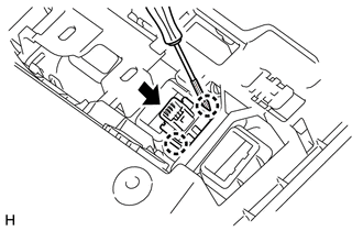
(b) Using a screwdriver, detach the 2 claws and remove the traction control switch (A-TRAC switch) from the map light assembly. HINT: Tape the screwdriver tip before use. |
|
Inspection
INSPECTION
PROCEDURE
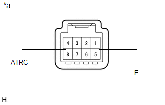
1. INSPECT TRACTION CONTROL SWITCH (A-TRAC SWITCH)
|
(a) Measure the resistance according to the value(s) in the table below. Standard Resistance:
If the result is not as specified, replace the traction control switch (A-TRAC switch). |
|
Installation
INSTALLATION
PROCEDURE
1. INSTALL TRACTION CONTROL SWITCH (A-TRAC SWITCH)
|
(a) Attach the 2 claws to install the traction control switch (A-TRAC switch) to the map light assembly. |
|
(b) Connect the 2 connectors.
2. INSTALL MAP LIGHT ASSEMBLY
(a) Attach the 2 clips to install the map light assembly.
(b) Install the screws.
3. INSTALL DRIVE MONITOR SWITCH
.gif)
 Steering Angle Sensor
Components
COMPONENTS
ILLUSTRATION
Removal
REMOVAL
PROCEDURE
1. PLACE FRONT WHEELS FACING STRAIGHT AHEAD
2. DISCONNECT CABLE FROM NEGATIVE BATTERY TERMINAL
CAUTION:
Wait at least 90 sec ...

Other materials about Toyota 4Runner:
Removal
REMOVAL
PROCEDURE
1. DISCONNECT CABLE FROM NEGATIVE BATTERY TERMINAL
CAUTION:
Wait at least 90 seconds after disconnecting the cable from the negative (-)
battery terminal to disable the SRS system (See page
).
NOTICE:
When disconnecting the cable, s ...
Parts Location
PARTS LOCATION
ILLUSTRATION
ILLUSTRATION
ILLUSTRATION
ILLUSTRATION
ILLUSTRATION
...

0.0097