Toyota 4Runner: Yaw Rate Sensor Communication Stop Mode
DESCRIPTION
|
Detection Item |
Symptom |
Trouble Area |
|---|---|---|
|
Yaw Rate Sensor Communication Stop Mode |
Either condition is met:
|
|
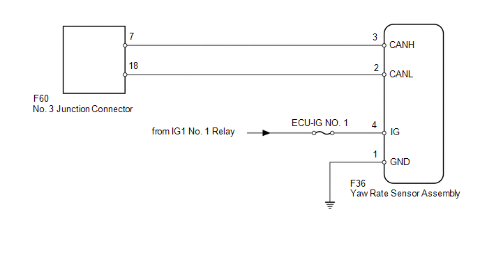
WIRING DIAGRAM
CAUTION / NOTICE / HINT
NOTICE:
Inspect the fuses for circuits related to this system before performing the following inspection procedure.
HINT:
Operating the ignition switch, any switches or any doors triggers related ECU and sensor communication with the CAN, which causes resistance variation.
PROCEDURE
|
1. |
DISCONNECT CABLE FROM NEGATIVE BATTERY TERMINAL |
(a) Disconnect the cable from the negative (-) battery terminal before measuring the resistances of the main wire and branch wire.
CAUTION:
Wait at least 90 seconds after disconnecting the cable from the negative (-) battery terminal to disable the SRS system.
NOTICE:
When disconnecting the cable, some systems need to be initialized after the cable
is reconnected (See page .gif) ).
).
|
.gif)
|
2. |
CHECK FOR OPEN IN CAN BUS WIRE (YAW RATE SENSOR ASSEMBLY BRANCH WIRE) |
|
(a) Disconnect the F36 yaw rate sensor assembly connector. |
|
(b) Measure the resistance according to the value(s) in the table below.
Standard Resistance:
|
Tester Connector |
Switch Condition |
Specified Condition |
|---|---|---|
|
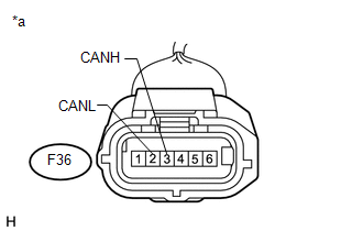
F36-3 (CANH) - F36-2 (CANL) |
Ignition switch off |
54 to 69 Ω |
|
*a |
Front view of wire harness connector (to Yaw Rate Sensor Assembly) |
| NG | .gif) |
REPAIR OR REPLACE YAW RATE SENSOR ASSEMBLY BRANCH WIRE OR CONNECTOR (CANH, CANL) |
|
|
3. |
CHECK HARNESS AND CONNECTOR (YAW RATE SENSOR ASSEMBLY - BATTERY AND BODY GROUND) |
|
(a) Connect the cable to the negative (-) battery terminal. NOTICE: When disconnecting the cable, some systems need to be initialized after
the cable is reconnected (See page |
|
(b) Measure the resistance according to the value(s) in the table below.
Standard Resistance:
|
Tester Connection |
Condition |
Specified Condition |
|---|---|---|
|
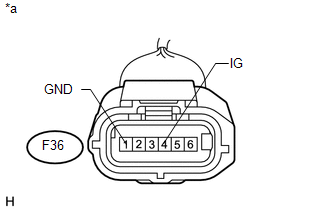
F36-1 (GND) - Body ground |
Always |
Below 1 Ω |
(c) Measure the voltage according to the value(s) in the table below.
Standard Voltage:
|
Tester Connection |
Switch Condition |
Specified Condition |
|---|---|---|
|
F36-4 (IG) - Body ground |
Ignition switch ON |
11 to 14 V |
|
*a |
Front view of wire harness connector (to Yaw Rate Sensor Assembly) |
| OK | |
REPLACE YAW RATE SENSOR ASSEMBLY |
| NG | |
REPAIR OR REPLACE HARNESS OR CONNECTOR |
 Steering Angle Sensor Communication Stop Mode
DESCRIPTION
Detection Item
Symptom
Trouble Area
Steering Angle Sensor Communication Stop Mode
Either condition is met:
" ...
 ECM Communication Stop Mode
DESCRIPTION
Detection Item
Symptom
Trouble Area
ECM Communication Stop Mode
Either condition is met:
"ECM (Engine)" ...
Other materials about Toyota 4Runner:
Inspection
INSPECTION
PROCEDURE
1. INSPECT FRONT NO. 1 SUSPENSION LOWER ARM SUB-ASSEMBLY LH
(a) As shown in the illustration, flip the ball joint stud back and forth
5 times before installing the nut.
(b) Using ...
Transponder Key Ecu
Components
COMPONENTS
ILLUSTRATION
Removal
REMOVAL
PROCEDURE
1. REMOVE INSTRUMENT PANEL REINFORCEMENT ASSEMBLY WITH AIR CONDITIONING UNIT
ASSEMBLY
(a) Remove the air conditioning unit (See page
).
2. REMOVE TRANSPONDER KEY ECU ASSEMBLY
...

0.0263