Toyota 4Runner: 4wd Control Ecu
Components
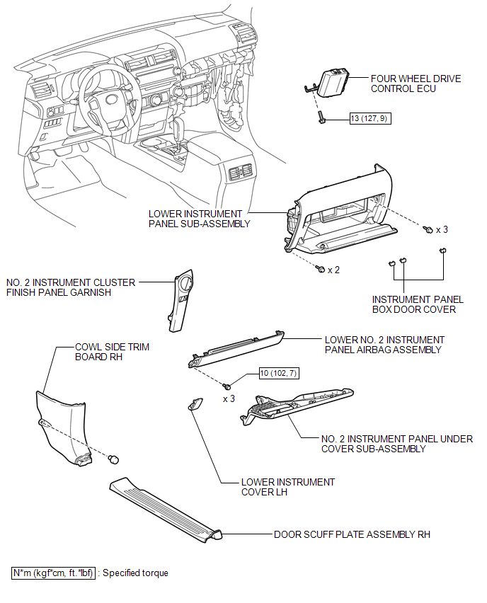
COMPONENTS
ILLUSTRATION
Removal
REMOVAL
PROCEDURE
1. REMOVE NO. 2 INSTRUMENT CLUSTER FINISH PANEL GARNISH
.gif)
2. REMOVE DOOR SCUFF PLATE ASSEMBLY RH
3. REMOVE COWL SIDE TRIM BOARD RH
4. REMOVE NO. 2 INSTRUMENT PANEL UNDER COVER SUB-ASSEMBLY
5. REMOVE LOWER INSTRUMENT COVER LH
6. REMOVE LOWER NO. 2 INSTRUMENT PANEL AIRBAG ASSEMBLY
7. REMOVE INSTRUMENT PANEL BOX DOOR COVER
8. REMOVE LOWER INSTRUMENT PANEL SUB-ASSEMBLY
9. REMOVE 4 WHEEL DRIVE CONTROL ECU NO.2
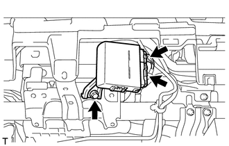
(a) Disconnect the 2 connectors.
(b) Remove the bolt and four wheel drive control ECU.
Installation
INSTALLATION
PROCEDURE
1. INSTALL 4 WHEEL DRIVE CONTROL ECU NO.2
(a) Install the four wheel drive control ECU with the bolt.
Torque:
13 N·m {127 kgf·cm, 9 ft·lbf}
(b) Connect the 2 connectors.
2. INSTALL LOWER INSTRUMENT PANEL SUB-ASSEMBLY
.gif)
3. INSTALL INSTRUMENT PANEL BOX DOOR COVER
4. INSTALL LOWER NO. 2 INSTRUMENT PANEL AIRBAG ASSEMBLY
5. INSTALL LOWER INSTRUMENT COVER LH
6. INSTALL NO. 2 INSTRUMENT PANEL UNDER COVER SUB-ASSEMBLY
7. INSTALL COWL SIDE TRIM BOARD RH
8. INSTALL DOOR SCUFF PLATE ASSEMBLY RH
9. INSTALL NO. 2 INSTRUMENT CLUSTER FINISH PANEL GARNISH


Other materials about Toyota 4Runner:
Vsc Off Switch
Components
COMPONENTS
ILLUSTRATION
Removal
REMOVAL
PROCEDURE
1. REMOVE DRIVE MONITOR SWITCH
2. REMOVE MAP LIGHT ASSEMBLY
3. REMOVE VSC OFF SWITCH
(a) Disconnect the 2 connectors.
...
All Door Entry Lock/Unlock Functions do not Operate, but Wireless Functions
Operate
DESCRIPTION
When the wireless operation can be used to lock and unlock the doors, the communication
line between the door control receiver and certification ECU is normal. When the
entry operation does not operate, one of the following may be the cause: 1 ...
0.0258