Toyota 4Runner: Acceleration Sensor Power Supply Voltage Malfunction (C1381)
DESCRIPTION
The skid control ECU receives signals from the yaw rate and acceleration sensor via the CAN communication system.
The yaw rate sensor has a built-in acceleration sensor and detects the vehicle's condition using 2 circuits (GL1, GL2).
If there is trouble in the bus lines between the yaw rate and acceleration sensor and the CAN communication system, DTCs U0123 (malfunction in CAN communication with the yaw rate sensor) and U0124 (malfunction in CAN communication with the acceleration sensor) are stored.
These DTCs are also stored when calibration has not been completed.
|
DTC Code |
DTC Detection Condition |
Trouble Area |
|---|---|---|
|
C1381 |
At a vehicle speed of more than 3 km/h (2 mph), the acceleration sensor power source malfunction signal is received for 10 seconds or more. |
|
WIRING DIAGRAM
Refer to DTCs C1232, C1243 and C1245 (See page
.gif) ).
).
CAUTION / NOTICE / HINT
NOTICE:
- When replacing the yaw rate and acceleration sensor, perform calibration
(See page ).
- Inspect the fuses for circuits related to this system before performing the following inspection procedure.
PROCEDURE
|
1. |
CHECK DTC (CAN COMMUNICATION SYSTEM) |
(a) Check for DTCs (See page ).
Result
|
Result |
Proceed to |
|---|---|
|
CAN DTC is not output |
A |
|
CAN DTC is output |
B |
| B | .gif) |
GO TO CAN COMMUNICATION SYSTEM (HOW TO PROCEED WITH TROUBLESHOOTING) |
|
.gif)
|
2. |
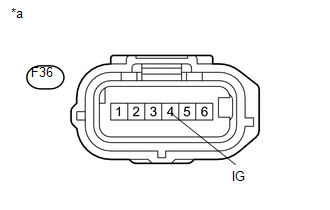
CHECK TERMINAL VOLTAGE (IG) |
(a) Disconnect the F36 yaw rate and acceleration sensor connector.
|
(b) Measure the voltage according to the value(s) in the table below. Standard Voltage:
|
|
| NG | |
REPAIR OR REPLACE HARNESS OR CONNECTOR (IG CIRCUIT) |
|
|
3. |
CHECK HARNESS AND CONNECTOR (GND TERMINAL) |
(a) Disconnect the F36 yaw rate and acceleration sensor connector.
(b) Measure the resistance according to the value(s) in the table below.
Standard Resistance:
|
Tester Connection |
Condition |
Specified Condition |
|---|---|---|
|
F36-1 (GND) - Body ground |
Always |
Below 1 Ω |
NOTICE:
Check the yaw rate and acceleration sensor signal after replacement (See page
).
| NG | |
REPAIR OR REPLACE HARNESS OR CONNECTOR (GND CIRCUIT) |
|
|
4. |
RECONFIRM DTC |
(a) Reconnect the yaw rate and acceleration sensor connector.
(b) Clear the DTCs (See page ).
(c) Start the engine.
(d) Perform a road test.
(e) Check if the same DTC is output (See page
).
|
Result |
Proceed to |
|---|---|
|
DTC C1381 is not output |
A |
|
DTC C1381 is output |
B |
| A | |
USE SIMULATION METHOD TO CHECK |
| B | |
REPLACE YAW RATE SAND ACCELERATION SENSOR |
 Stop Light Control Relay Malfunction (C1380)
DESCRIPTION
Upon receiving the hill-start assist control operating signal from the master
cylinder solenoid (skid control ECU), the Stop light control relay (Stop light switch
assembly) contact t ...
 Front Speed Sensor RH Malfunction (C1401,C1271,C1272,C1402)
DESCRIPTION
The speed sensor detects the wheel speed and sends the appropriate signals to
the skid control ECU. These signals are used for brake control.
The speed sensor rotors have rows of alter ...
Other materials about Toyota 4Runner:
Open or Short in Front Speed Sensor RH Circuit (C1405,C1406)
DESCRIPTION
Refer to DTCs C1401 and C1402 (See page ).
DTC Code
DTC Detection Condition
Trouble Area
C1405
C1406
Either condition is met:
An open in the speed sensor signal circui ...
Pressure Control Solenoid "B" Electrical (Shift Solenoid Valve SL2) (P0778)
DESCRIPTION
Shifting from 1st to 5th is performed in combination with the ON and OFF operation
of the shift solenoid valves SL1, SL2, S1, S2 and SR, which are controlled by the
ECM. If an open or short circuit occurs in one of the shift solenoid valves, t ...
0.0276